Detailed descriptions
16.1 Motherboard
SIMATIC HMI IPC677C
Operating Instructions, 04/2013, A5E02722710-04
209
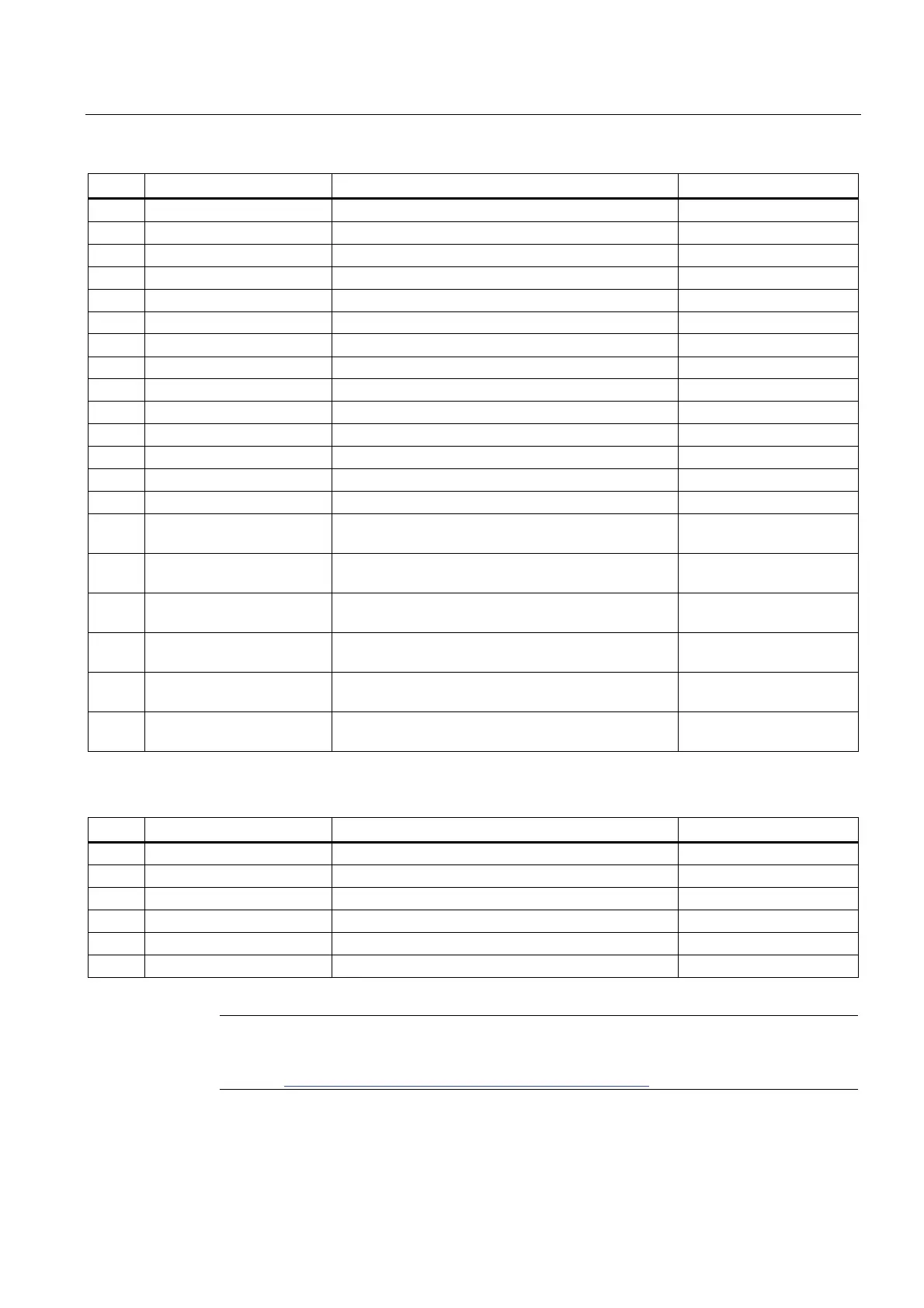
Pin no. Short description Meaning Input / Output
7 Reserved Reserved -
8 Reserved Reserved -
9 Reserved Reserved -
10 Reserved Reserved -
11 P5V_fused +5 V (fused) Output
12 USB_D1M USB data channel 10 Input / Output
13 USB_D1P USB data+, channel 10 Input / Output
14 GND Ground -
15 LCD_SEL0 Display Type-Select Signal 0 Input
16 LCD_SEL1 Display Type-Select Signal 1 Input
17 LCD_SEL2 Display Type-Select Signal 2 Input
18 LCD_SEL3 Display Type-Select Signal 3 Input
19 RESET_N Reset signal (active low) Input
20 reserved Reserved -
21 HD_LED HD LED, anode with 1 kOhm in series on the
motherboard
Output
22 DP_LED MPI/DP LED, anode via 1 kOhm in series on the
motherboard
Output
23 Ethernet_LED Ethernet LED, anode with 1 kOhm in series on the
motherboard
Output
24 TEMP_ERR Temperature error LED, anode with 1 kOhm in series
on the motherboard
Output
25 RUN_R Watchdog error LED, anode with 1 kOhm in series on
the motherboard
Output
26 RUN_G Watchdog OK LED, anode with 1 kOhm in series on
the motherboard
Output
Pin Assignment of the USB 2.0 interface, X42
Pin no. Short description Meaning Input / Output
1 VCC + 5 V, fused Output
2 USB5 USB5_M Input / Output
3 USB5 USB5_P Input / Output
4 GND Ground -
S1 S Shield -
S2 S1 Shield -
Note
For detailed information on the pin assignments of the interfaces, please contact Customer
Support (http://www.siemens.com/automation/service&support
) or the Repair Center.
 Loading...