Planning the use
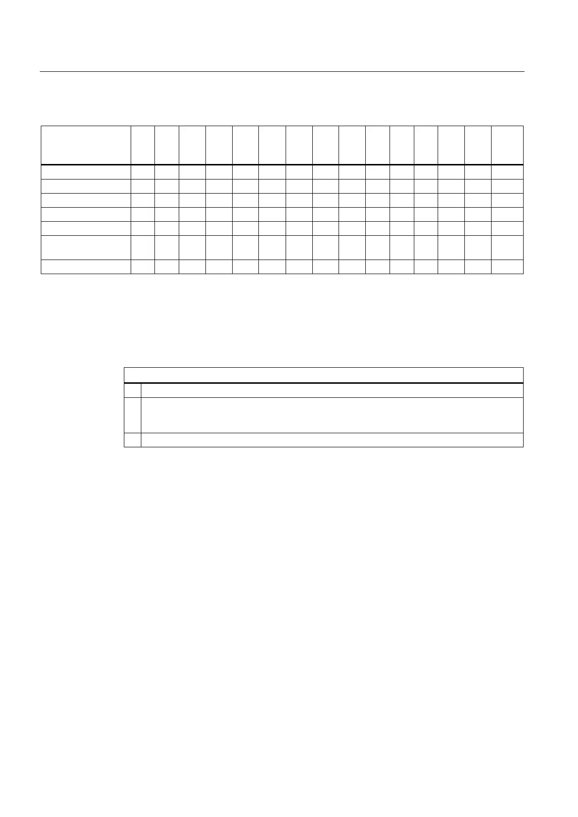
3.5 Mounting cutout
SIMATIC HMI IPC677C
34 Operating Instructions, 04/2013, A5E02722710-04
Table 3- 2 Dimensions for the mounting cut-out in mm
Control unit L1 L2 L3
1)
L4
1)
L5 L6
2)
L7
2)
L8
2)
L9
2)
A1 A2 S1 S2
S3
S4
S5
3)
S6
3)
S7
3)
Tolerance ±1 +1 ±0.2 ±0.2 ±0.5 ±0.5 ±0.5 ±0.5 +1 ±1 ±1 ±1 ±1 ±1 ±1
Key panel 12" TFT 450 290 465 235 112 — — — — 16 10 78 78 56 —
Key panel 15" TFT 450 321 465 279 112 186 135 25 165 16 17 51 51 56 —
Touch panel 12" TFT 368 290 — — 112 — — — — 16 10 19 35 56 —
Touch panel 15" TFT 450 290 465 235 112 — — — — 16 10 81 81 56 —
Touch panel 15" TFT
INOX
450 290 465 235 112 — — — — 16 10 — — — —
Touch panel 19" TFT 450 380 465 235 112 — — — — 16 10 46 46 — 46
1)
M6 thread or drill holes with a diameter of 7 mm
2)
Cut-outs for the shafts of the insert strips are only necessary for 15" key panels.
3)
Two clamps necessary for vertically securing clamps only for 19" touch panel fronts.
Preparing the mounting cut-out
Steps for preparing the mounting cut-out
1 Select a location suitable for mounting, taking into account the mounting position.
2 On the basis of the dimensions, check whether the required screw and pressure points on the
rear and the seal area are easily accessible after the completion of the mounting cut-out.
Otherwise the mounting cut-out is useless.
3 Complete the mounting cut-out in accordance with the dimensions.
 Loading...