Product description
1.4 External design of the device
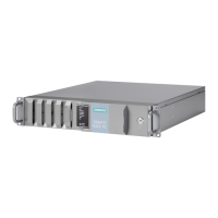
SIMATIC IPC627E
Operating Instructions, 12/2018, A5E44297201-AA
21
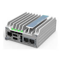
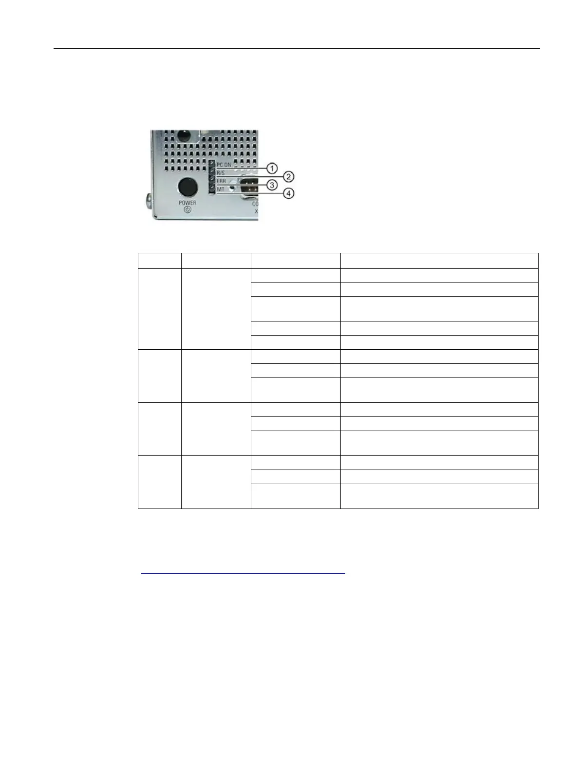
1.4.3 Status displays
The status display consists of four multi-colored LEDs.
PC ON/WD
Flashing
BIOS in POST, power switch on
Watchdog status display: active
②
RUN/STOP
or L1
Can be controlled by user program
Yellow Can be controlled by controller program (e.g.
③
ERROR
or L2
Flashing red Can be controlled by user program or controller
MAINT
or L3
Red Can be controlled by controller program (e.g.
For additional information on controlling the LEDs or the NVRAM with a Windows operating
system, please refer to the chapter "Buffer memory NVRAM (optional) (Page 69)". Example
programs for controlling the LEDs under Windows operating systems are available on the
Internet at the following address: Technical support
(https://support.industry.siemens.com/cs/ww/en/)