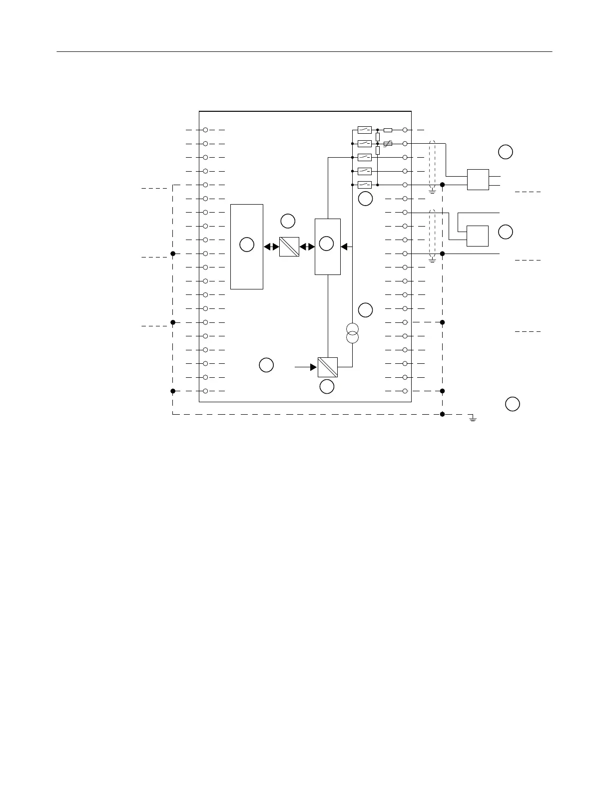
Wiring: 2-wire and 4-wire transducers for current measurement
/
0
/
0
'08
8
,
6
ದ
0
0
ದ
8
,
6
ದ
0
0
ದ
8
,
6
ದ
0
0
ದ
8
,
6
ದ
0
0
ದ
&+
&+
&+
&+
8
,
6
ದ
0
0
ದ
8
,
6
ದ
0
0
ದ
8
,
6
ದ
0
0
ದ
8
,
6
ದ
0
0
ದ
&+
&+
&+
&+
'08
① 4-wire transducer (0/4 mA to 20 mA or ± 20 mA)
② 2-wire transducer (4 mA to 20 mA)
③ Equipotential bonding
④ Internal supply
⑤ + 5 V from backplane bus
⑥ Logic and backplane bus interface
⑦ Electrical isolation
⑧ Multiplexer
⑨ Analog to Digital Converter (ADC)
⑩ Current source
Figure 10-7 Block diagram and wiring diagram
ET 200PA SMART I/O modules
10.4 Analog input modules
ET 200PA SMART
Operating Instructions, 06/2019, A5E34192013-AB 155
 Loading...


