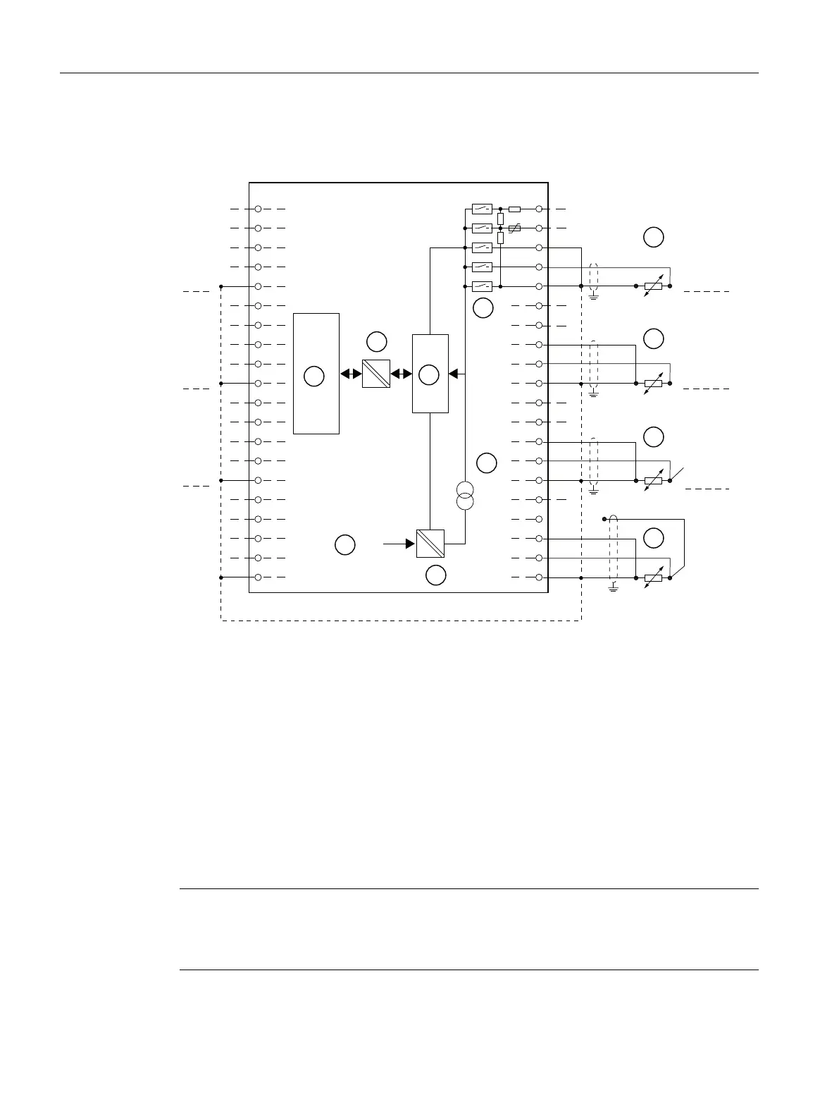
Wiring: Resistance measurement with 2-, 3- and 4-wire connection
The following connection possibilities also apply to silicon temperature sensors and PTCs.
8
,
6
ದ
0
0
ದ
8
,
6
ದ
0
0
ದ
8
,
6
ದ
0
0
ದ
8
,
6
ದ
0
0
ದ
&+
&+
&+
&+
8
,
6
ದ
0
0
ದ
8
,
6
ದ
0
0
ದ
8
,
6
ದ
0
0
ದ
8
,
6
ದ
0
0
ದ
&+
&+
&+
&+
① 2-wire connection. Insert a bridge between M and S (no line resistance compensation).
② 3-wire connection
③ 4-wire connection. The fourth line may not be wired (remains unused)
④ 4-wire connection. The fourth line is routed to the terminal strip in the cabinet but is not wired.
⑤ Internal supply
⑥ + 5 V from backplane bus
⑦ Logic and backplane bus interface
⑧ Electrical isolation
⑨ Multiplexer
⑩ Analog to Digital Converter (ADC)
⑪ Current source
Figure 10-8 Block diagram and terminal diagram
Note
It is not necessary to interconnect the M- terminals when measuring using resistors, resistance
thermometers, PTCs, or silicon temperature sensors. However, interconnection of the M-
terminals may enhance interference immunity.
ET 200PA SMART I/O modules
10.4 Analog input modules
ET 200PA SMART
156 Operating Instructions, 06/2019, A5E34192013-AB
 Loading...


