EasyManuals Logo

Siemens SIMATIC PCS 7 Operating Instructions

Siemens SIMATIC PCS 7
226 pages
To Next Page IconTo Next Page
To Previous Page IconTo Previous Page
Page #203 background imageLoading...
Page #203 background image
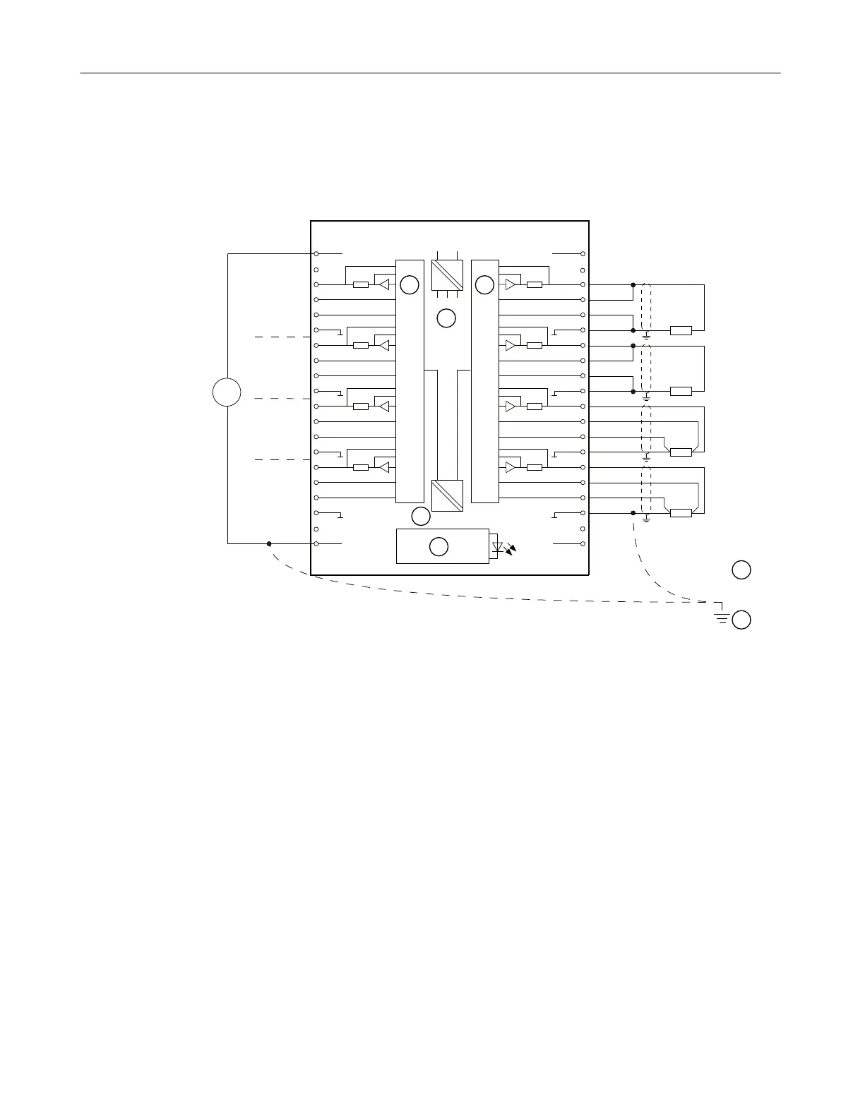
As of product version 3: Wiring: 2-wire and 4-wire connection for voltage output
The following picture shows
The 2-wire connection without compensation of the line resistances and
The 4-wire connection with compensation of the line resistances.
/0
9
0
0
&+
&+
&+
&+











6)




















&+
&+
&+
&+
6

49

6
0
$1$
6

49

6
0
$1$
6

49

6
0
$1$
6

49

6
0
$1$
9
'&
/
DAC
Internal supply
Equipotential bonding
Functional ground
Backplane bus interface
Electrical isolation
Figure 10-14 Wiring and block diagram
ET 200PA SMART I/O modules
10.5 Analog output modules
ET 200PA SMART
Operating Instructions, 06/2019, A5E34192013-AB 203

Table of Contents

Other manuals for Siemens SIMATIC PCS 7

Questions and Answers:

Question and Answer IconNeed help?

Do you have a question about the Siemens SIMATIC PCS 7 and is the answer not in the manual?

Siemens SIMATIC PCS 7 Specifications

General IconGeneral
BrandSiemens
ModelSIMATIC PCS 7
CategoryControl Systems
LanguageEnglish

Related product manuals