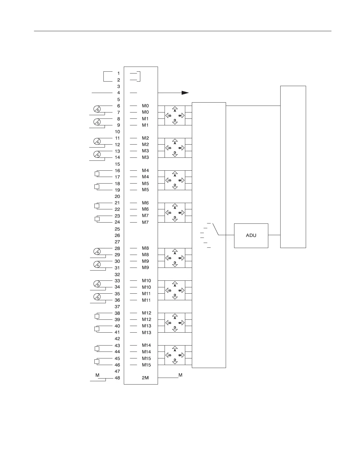
Circuit diagram for SM 431; AI 16 x 13 bit
*
*
*
*
*
*
*
*
*
Tr
Tr
Tr
Tr
Tr
Tr
Tr
Tr
Tr = Transducer = Measuring
transducer
*Voltage/current sensor and ground
must be connected to building ground
of the rack
Measuring range module
Multiplexer
Control and backplane bus connection
Figure 5-30 Circuit diagram for SM 431; AI 16 x 13 bit
Analog modules
5.22 Analog input module SM 431; AI 16 x 13 Bit (6ES7431-0HH00-0AB0)
S7-400 Automation System Module Data
Reference Manual, Ausgabe 11/2016, A5E00850736-08 265

 Loading...


