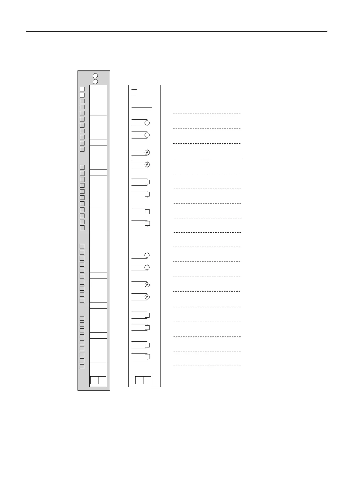
Connection diagram for SM 431; AI 16 x 13 bit
M1+
M2-
M3-
M4-
M5-
M6-
M7-
CH0
CH1
CH2
CH3
CH4
CH5
CH6
CH7
L+
M0+
M0-
M1-
M2+
M3+
M4+
M5+
M6+
M7+
M
M8-
M9-
M8+
M9+
M10-
M11-
M10+
M11+
M12-
M13-
M12+
M13+
M14-
M15-
M14+
M15+
CH8
CH9
CH10
CH11
CH12
CH13
CH14
CH15
L+
M
29
30
31
32
33
34
35
36
37
39
40
41
42
43
44
45
46
47
48
38
1
2
3
4
5
6
7
8
9
10
11
12
13
14
15
16
17
18
19
20
21
22
23
24
25
26
27
28
Tr
Tr
Tr
Tr
Tr
Tr
Tr
Tr
Voltage measurement
Current measurement
Word 0
Word 2
Word 4
Word 6
Word 8
Word 10
Word 12
Word 14
Word 16
Word 18
Word 20
Word 22
Word 24
Word 26
Word 28
Word 30
Figure 5-31 Connection diagram for SM 431; AI 16 x 13 bit
Analog modules
5.22 Analog input module SM 431; AI 16 x 13 Bit (6ES7431-0HH00-0AB0)
S7-400 Automation System Module Data
266 Reference Manual, Ausgabe 11/2016, A5E00850736-08

 Loading...


