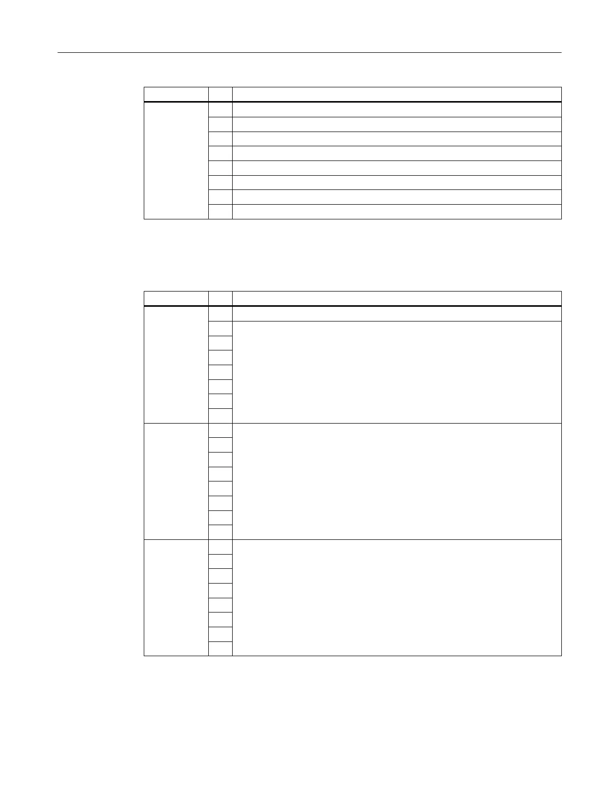
Byte Bit Meaning
Byte 3 7 0
6 Hardware interrupt lost
5 0
4 ADC/DAC error
3 0
2 EPROM error
1 0
0 0
Bytes 4 and 7 of the SM 431; AI 8 x RTD x 16 bit
Table B-22 Bytes 4 to 7 of the diagnostic data of the SM 431; AI 8 x RTD x 16 bit
Byte Bit Meaning
Byte 4 7 0
6 Channel type B#16#71: Analog input
5
4
3
2
1
0
Byte 5 7 Number of diagnostics bits that the module outputs per channel: 16 bits long
0
Byte 6 7 Number of channels of the same type in one module: 8 channels
0
Diagnostic data of signal modules
B.5 Diagnostic data of the analog input modules as of byte 2
S7-400 Automation System Module Data
Reference Manual, Ausgabe 11/2016, A5E00850736-08 423

 Loading...


