Byte Bit Meaning
Byte 7 7 Channel error 7
6 Channel error 6
5 ...
4 ...
3 ...
2 ...
1 Channel error 1
0 Channel error 0
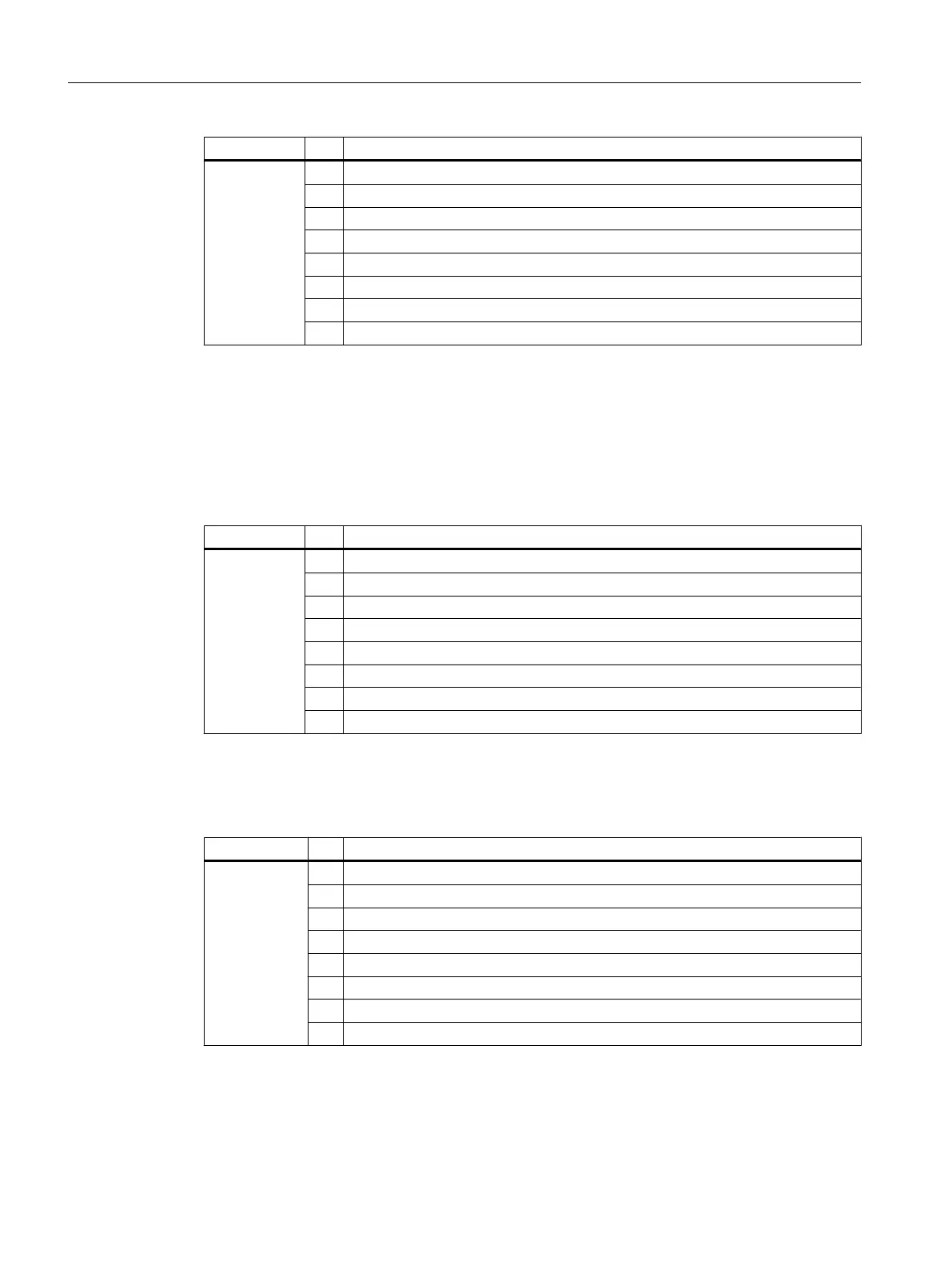
Bytes 8 and 23 of the SM 431; AI 8 x RTD x 16 bit
Data record 1 contains the channel-specific diagnostic data, starting at bytes 8 to 23. The
following table shows the assignment of the even diagnostic bytes (bytes 8, 10, to 22) for a
channel of the module.
Table B-23 Even diagnostic byte for a channel of the SM 431; AI 8 x RTD x 16 bit
Byte Bit Meaning
Byte 8-23
even
7 Overflow
6 Underflow
5 0
4 Wire break
3 0
2 0
1 0
0 Configuring/parameter assignment error
The following table shows the assignment of the odd diagnostic bytes (bytes 9, 11, to 23) for
a channel of the module.
Table B-24 Odd diagnostic byte for a channel of the SM 431; AI 8 x RTD x 16 bit
Byte Bit Meaning
Byte 8-23
odd
7 User calibration does not correspond to the parameter assignment
6 Open conductor in the current source
5 0
4 Underrange or overrange
3 Run time calibration error
2 Open conductor in - direction
1 Open conductor in + direction
0 User connection not wired
Diagnostic data of signal modules
B.5 Diagnostic data of the analog input modules as of byte 2
S7-400 Automation System Module Data
424 Reference Manual, Ausgabe 11/2016, A5E00850736-08

 Loading...


