PLC concepts
4.5 Status LEDs
S7-200 SMART
102 System Manual, V2.3, 07/2017, A5E03822230-AF
Each digital EM provides a DIAG LED that indicates the status of the module:
● Green indicates that the module is operational
● Red indicates that the module is defective or non-operational
Each analog EM provides an I/O Channel LED for each of the analog inputs and outputs.
● Green indicates that the channel has been configured and is active
● Red indicates an error condition of the individual analog input or output
In addition, each analog EM provides a DIAG LED that indicates the status of the module:
● Green indicates that the module is operational
● Red indicates that the module is defective or non-operational
The EM DP01 has a different set of LEDs. See LED status indicators for the EM DP01
PROFIBUS DP (Page 437).
The EM detects the presence or absence of power to the module (field-side power, if
required).
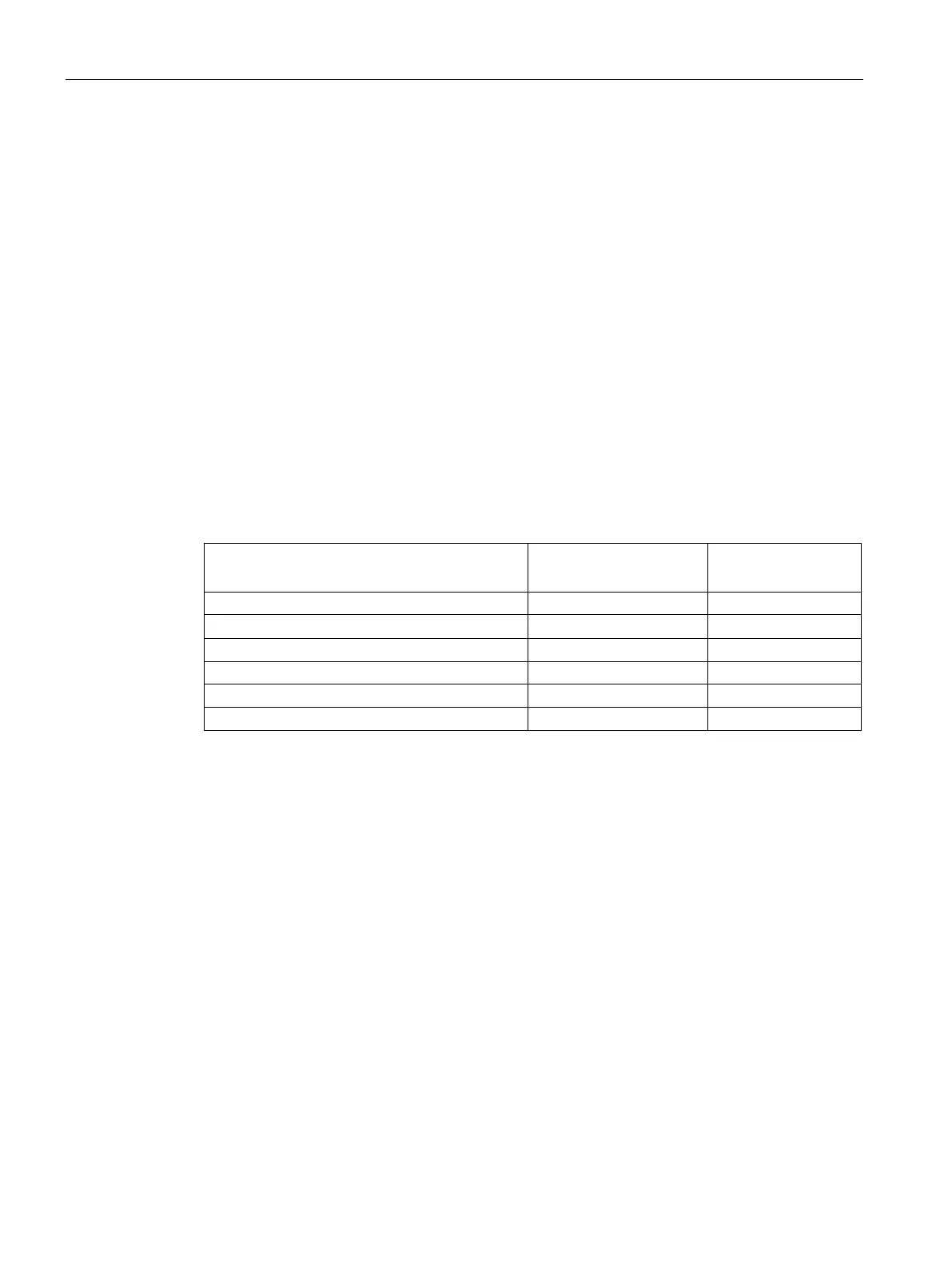
Table 4- 25 Status LEDs for a expansion module (EM)
I/O Channel
(Red / Green)
Field-side power is off *
Not configured or update in progress Flashing green Off
Module configured with no errors
I/O error (with diagnostics enabled)
I/O error (with diagnostics disabled)
* Status is only supported on analog signal modules.

 Loading...


