Technical specifications
A.11 S7-200 SMART cables
S7-200 SMART
System Manual, V2.3, 07/2017, A5E03822230-AF
781
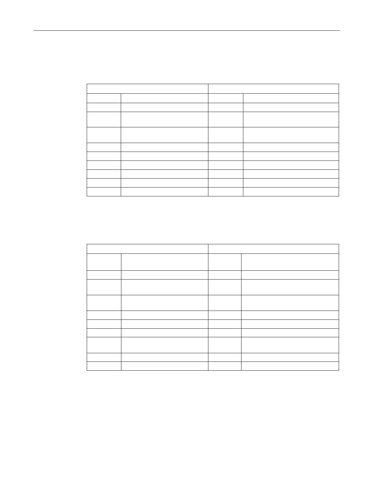
RS-232/PPI Multi-Master Cable
Table A- 164 RS-232/PPI Multi-Master Cable - Pin-outs for RS-485 to RS-232 Local Mode Connector
RS-232 Local Connector Pin-out
1 No connect 1 Data Carrier Detect (DCD) (not used)
2 24 V Return (RS-485 logic
2 Receive Data (RD) (output from
3 Signal B (RxD/TxD+) 3 Transmit Data (TD) (input to PC/PPI
cable)
Data Terminal Ready (DTR)
1
Ground (RS-232 logic ground)
1
Request To Send (RTS) (not used)
Clear To Send (CTS) (not used)
Ring Indicator (RI) (not used)
1
Pins 4 and 6 are connected internally.
Table A- 165 RS-232/PPI Multi-Master Cable - Pin-outs for RS-485 to RS-232 Remote Mode Con-
nector
RS-232 Remote Connector Pin-out
1
Data Carrier Detect (DCD) (not used)
2 24 V Return (RS-485 logic
2 Receive Data (RD) (input to
3 Signal B (RxD/TxD+) 3 Transmit Data (TD) (output from
Data Terminal Ready (DTR)
2
Ground (RS-232 logic ground)
2
7 24 V Supply 7 Request To Send (RTS) (output from
PC/PPI cable)
Clear To Send (CTS) (not used)
9 Protocol select 9 Ring Indicator (RI) (not used)
A conversion from female to male, and a conversion from 9-pin to 25-pin is required for modems.
2
Pins 4 and 6 are connected internally.

 Loading...


