Communication
8.5 PROFIBUS
S7-200 SMART
428 System Manual, V2.3, 07/2017, A5E03822230-AF
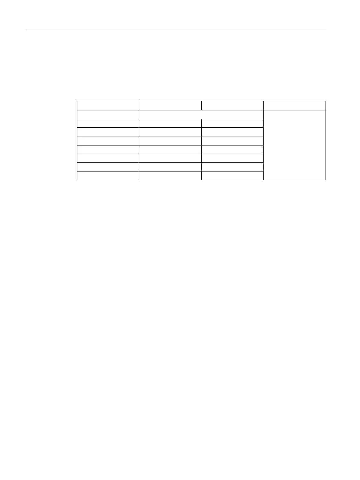
The following table lists the configurations that are supported by the S7-200 SMART
EM DP01 PROFIBUS DP module:
Table 8- 2 EM DP01 PROFIBUS DP configuration options
Buffer consistency
1
4 16 bytes 16 bytes
6 64 bytes 64 bytes
1
All EM DP01 configurations are buffer consistent.
We can mix and match any two of these configurations in an EM DP01 configuration. Here
are two examples:
● A configuration of 32 bytes input and output plus a configuration of 8 bytes input and
output yields a total of 40 input bytes and 40 output bytes.
● A configuration of 122 bytes input and output plus a configuration of 122 bytes input and
output yields a total of 244 input bytes and 244 output bytes.
The EM DP01 allows a maximum of 244 input bytes and 244 output bytes. If you use two
configurations for the EM DP01, all of the input data is contiguous, and all of the output data
is contiguous. Refer to "Example of V memory and I/O address area" (Page 433) for further
information.

 Loading...


