Installation
3.3 Installation and removal procedures
S7-200 SMART
System Manual, V2.3, 07/2017, A5E03822230-AF
55
Installing and removing a signal board or battery board
The CPU models CPU CR20s, CPU CR30s, CPU CR40s, and CPU CR60s do not support
the use of expansion modules, signal boards or battery boards.
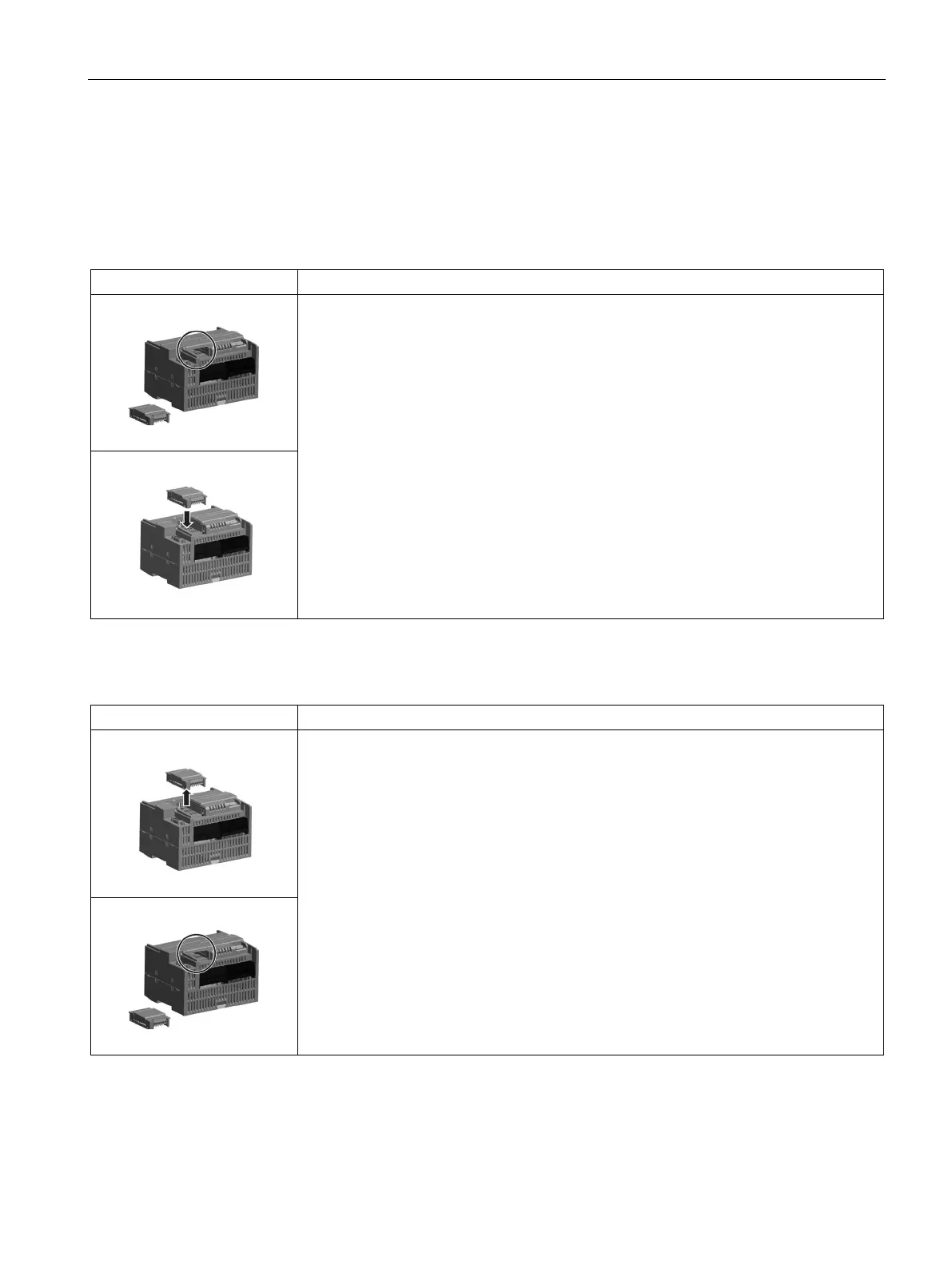
Table 3- 3 Installing a signal board on a CPU
Follow the steps below to install a signal board or battery board
1. Ensure that the CPU and all S7-200 SMART equipment are disconnected from electri-
cal power.
2. Remove the top and bottom terminal block covers from the CPU.
3. Place a screwdriver into the slot on top of the CPU at the rear of the cover.
4. Gently pry the cover up and remove it from the CPU.
5. Place the signal board or battery board straight down into its mounting position in the
top of the CPU.
6. Firmly press the module into position until it snaps into place.
7. Replace the terminal block covers.
Table 3- 4 Removing a signal board or battery board on a CPU
Follow the steps below to remove a signal board or battery board
1. Ensure that the CPU and all S7-200 SMART equipment are disconnected from electri-
cal power.
2. Remove the top and bottom terminal block covers from the CPU.
3. Place a screwdriver into the slot on top of the module.
4. Gently pry the module up to disengage it from the CPU.
5. Remove the module straight up from its mounting position in the top of the CPU.
6. Replace the cover onto the CPU.
7. Replace the terminal block covers.

 Loading...


