Product overview
1.1 S7-200 SMART CPU
S7-200 SMART
18 System Manual, V2.3, 07/2017, A5E03822230-AF
The CPU combines a microprocessor, an integrated power supply, input circuits, and output
circuits in a compact housing to create a powerful Micro PLC. After you have downloaded
your program, the CPU contains the logic required to monitor and control the input and
output devices in your application.
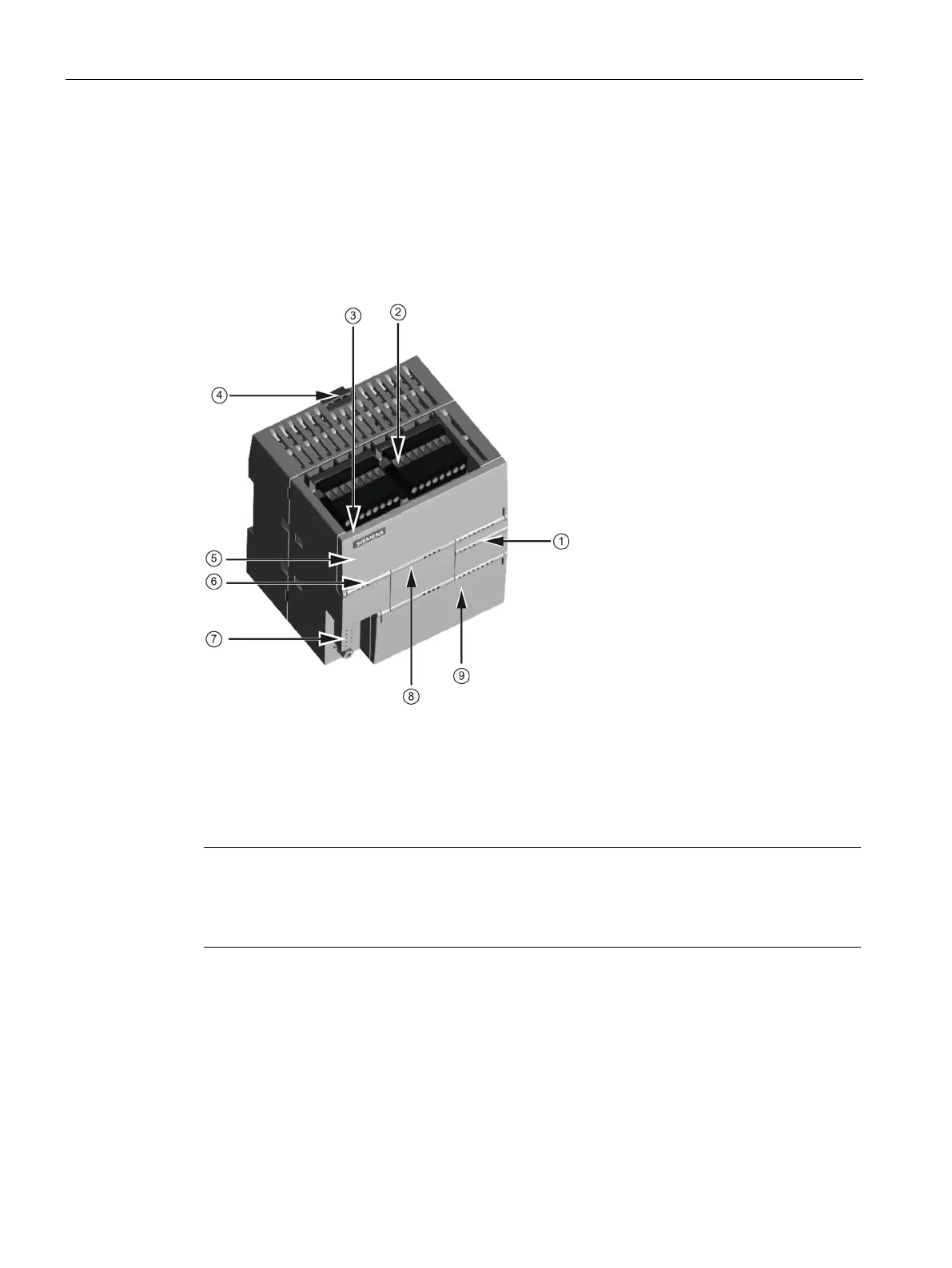
communication port
Clip for installation on a
standard (DIN) rail
(under door): LINK, Rx/Tx
Status LEDs: RUN, STOP and
ERROR
eader (under
The CPU provides different models with a diversity of features and capabilities that help you
create effective solutions for your varied applications. The different models of CPUs are
shown below. For detailed information about a specific CPU, see the technical specifications
(Page 685).
Note
CPU CR40 and CPU CR60
S7
-200 SMART CPU firmware release V2.3 does not apply to the CPU CR40 and CPU

 Loading...


