Communication
8.6 RS485
S7-200 SMART
462 System Manual, V2.3, 07/2017, A5E03822230-AF
Biasing and terminating the network cable
Siemens provides two types of network connectors that you can use to easily connect
multiple devices to a network:
● Standard network connector
● Connector that includes a port which allows you to connect an HMI device to the network
without disturbing any existing network connections
The programming port connector passes all signals (including the power pins) from the
S7-200 SMART CPU through to the programming port, which is especially useful for
connecting devices that draw power from the S7-200 SMART CPU (such as a TD 400C).
Both connectors have two sets of terminal screws to allow you to attach the incoming and
outgoing network cables. Both connectors also have switches to bias and terminate the
network selectively. The following shows typical biasing and termination for the cable
connectors.
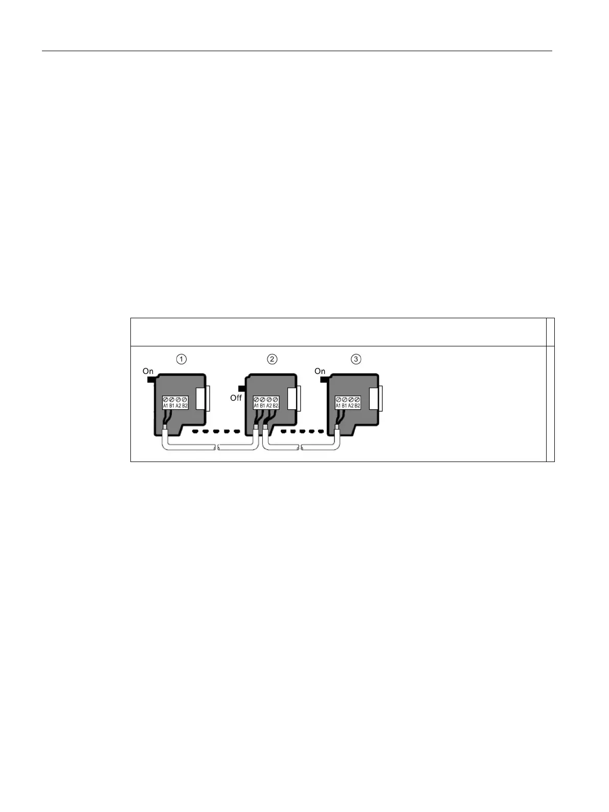
Table 8- 19 Biasing and termination for cable connectors
Cable must be terminated and biased at both ends. Bare shielding: Approximately 12 mm (1/2 in)
must contact the metal guides of all locations.
Switch position = On: Terminated and biased
Switch position = Off: No termination or bias
③ Switch position = On: Terminated and biased

 Loading...


