Program instructions
7.1 Bit logic
S7-200 SMART
172 System Manual, V2.3, 07/2017, A5E03822230-AF
FBD editor input assignment
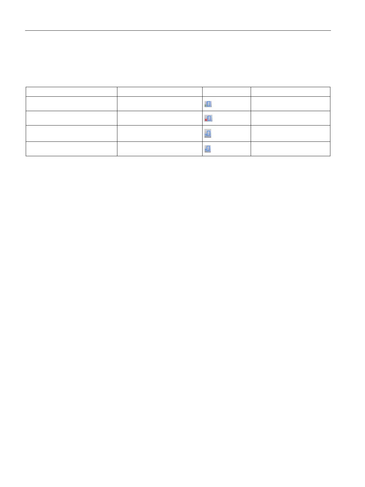
The editor feature described in the following table is active only if an input stub is selected
and colored red, inside the FBD box cursor.
Add input On box
+
Remove input On box and bottom input
-
Toggle negate input On box and input
F11
Toggle immediate input On box and input
CTRL F11
Bit logic input examples (Page 182)
Logic stack overview (Page 172)
The STEP 7-Micro/WIN SMART program compiler uses the logic stack to transform the
graphical I/O networks of LAD and FBD programs into STL (statement list) programs. The
resultant STL program is logically the same as the original LAD or FBD graphical network
and can be executed as a program list. All successfully compiled LAD and FBD programs
have generated the underlying STL program and can be viewed as LAD, FBD, or STL.
For LAD and FBD editing, the STL logic stack instructions are automatically generated and
the programmer does not need to use the logic stack instructions.
You can also create STL programs directly with the STL editor. An STL programmer uses
the logic stack instructions directly. Combination logic can be created in the STL editor that is
too complex to be viewed in the LAD or FBD editor, but may be necessary for special
applications.
All successfully compiled LAD and FBD programs can be viewed in STL, but not all
successfully compiled STL programs can be viewed in LAD or FBD.

 Loading...


