PLC device configuration
6.1 Configuring the operation of the PLC system
S7-200 SMART
System Manual, V2.3, 07/2017, A5E03822230-AF
151
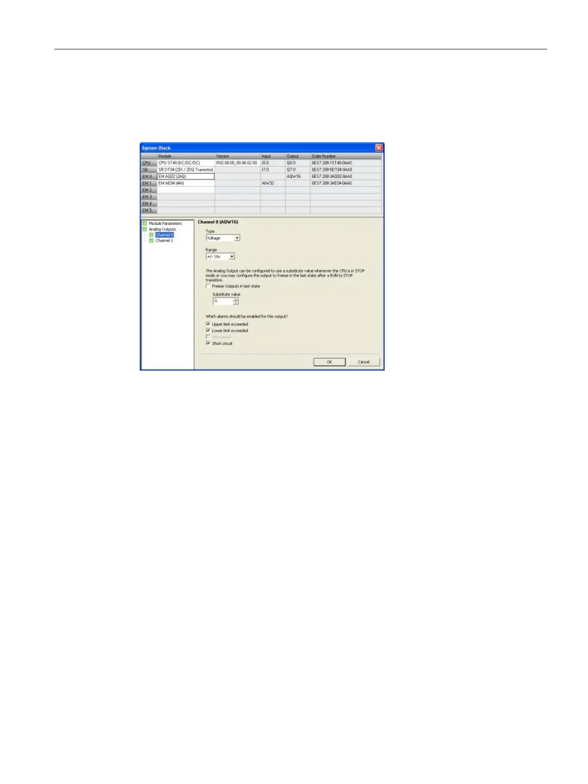
Configuring the analog outputs
Click the Analog Outputs node of the system block (Page 133) dialog to configure options for
an analog output module that you have selected in the top section.
Analog type configuration
For each analog output channel you configure the type to be either voltage or current.
You then configure either the voltage range or the current range for the channel. You can
choose one of the following value ranges:
● +/- 10 V
● 0 - 20 mA
Output behavior in STOP mode
You can set analog output points to a specific value when the CPU is in STOP mode or
preserve the output states that existed before the transition to STOP mode.
You have two ways to set the analog output behavior in STOP mode:
● Freeze outputs in last state: Click this checkbox to have all analog outputs frozen to their
last values on a RUN-to-STOP transition.
● Substitute value: If the "Freeze outputs in last state" checkbox is not checked, you can
enter a value (-32512 to 32511) that is applied to the output whenever the CPU is in
STOP mode. The default substitute value is 0.

 Loading...


