EasyManua.ls Logo

Siemens SIMATIC S7 - Wiring Diagrams for Sink and Source Input, and Relay Output

Siemens SIMATIC S7
866 pages
To Next Page IconTo Next Page
To Previous Page IconTo Previous Page
Loading...
Technical specifications
A.2 S7-200 SMART CPUs
S7-200 SMART
724 System Manual, V2.3, 07/2017, A5E03822230-AF
Pin
X10
X11
X12
X13
11
DI b.1
DI d.5
3L
--
12 DI b.2 DI d.6 DQ b.0 --
13
DI b.3
DI d.7
DQ b.1
--
14 DI b.4 DI e.0 DQ b.2 --
15
DI b.5
DI e.1
DQ b.3
--
16
DI b.6
DI e.2
4L
--
17
DI b.7
DI e.3
DQ b.4
--
18
DI c.0
L1 / 120 - 240 V AC
DQ b.5
--
19
DI c.1
N / 120 - 240 V AC
DQ b.6
--
20
DI c.2
Functional Earth
DQ b.7
--
A.2.5
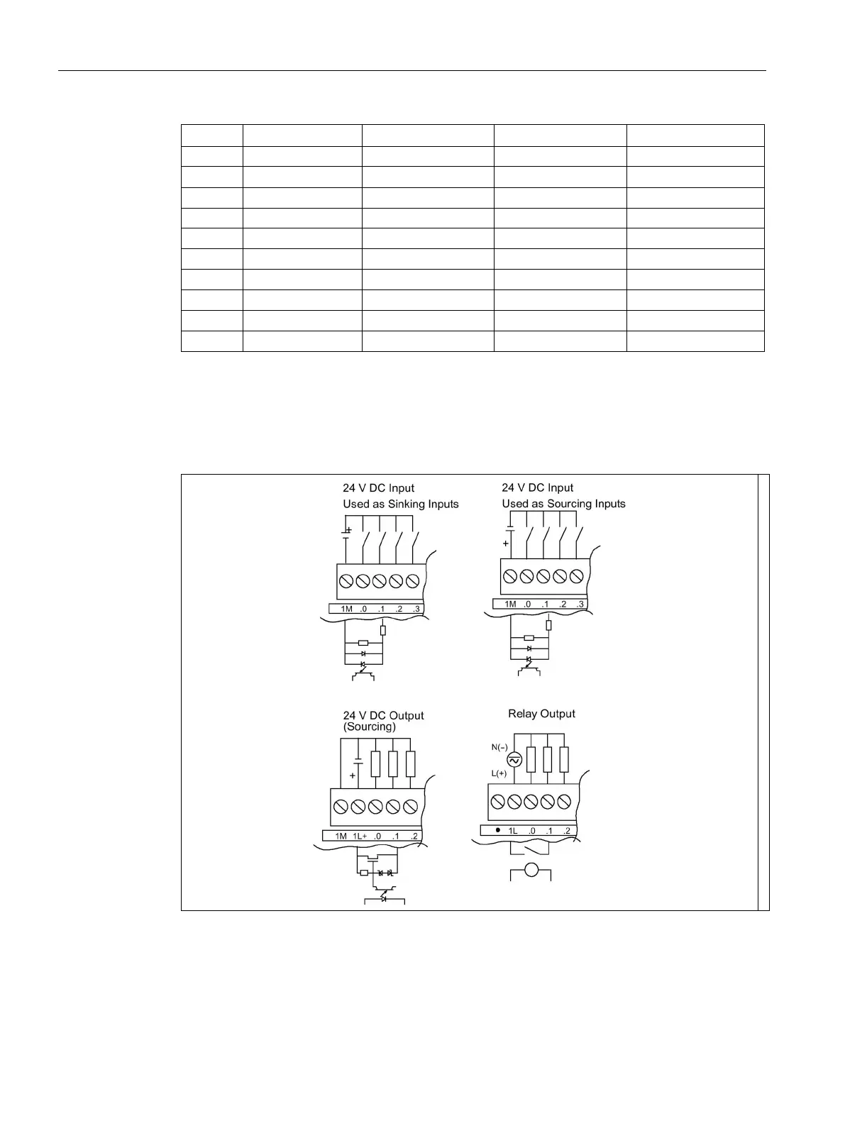
Wiring diagrams for sink and source input, and relay output
Table A- 68 Wiring diagrams for sink input, source input, and relay output

Table of Contents

Other manuals for Siemens SIMATIC S7

Related product manuals