Technical specifications
A.2 S7-200 SMART CPUs
S7-200 SMART
System Manual, V2.3, 07/2017, A5E03822230-AF
689
Digital inputs and outputs
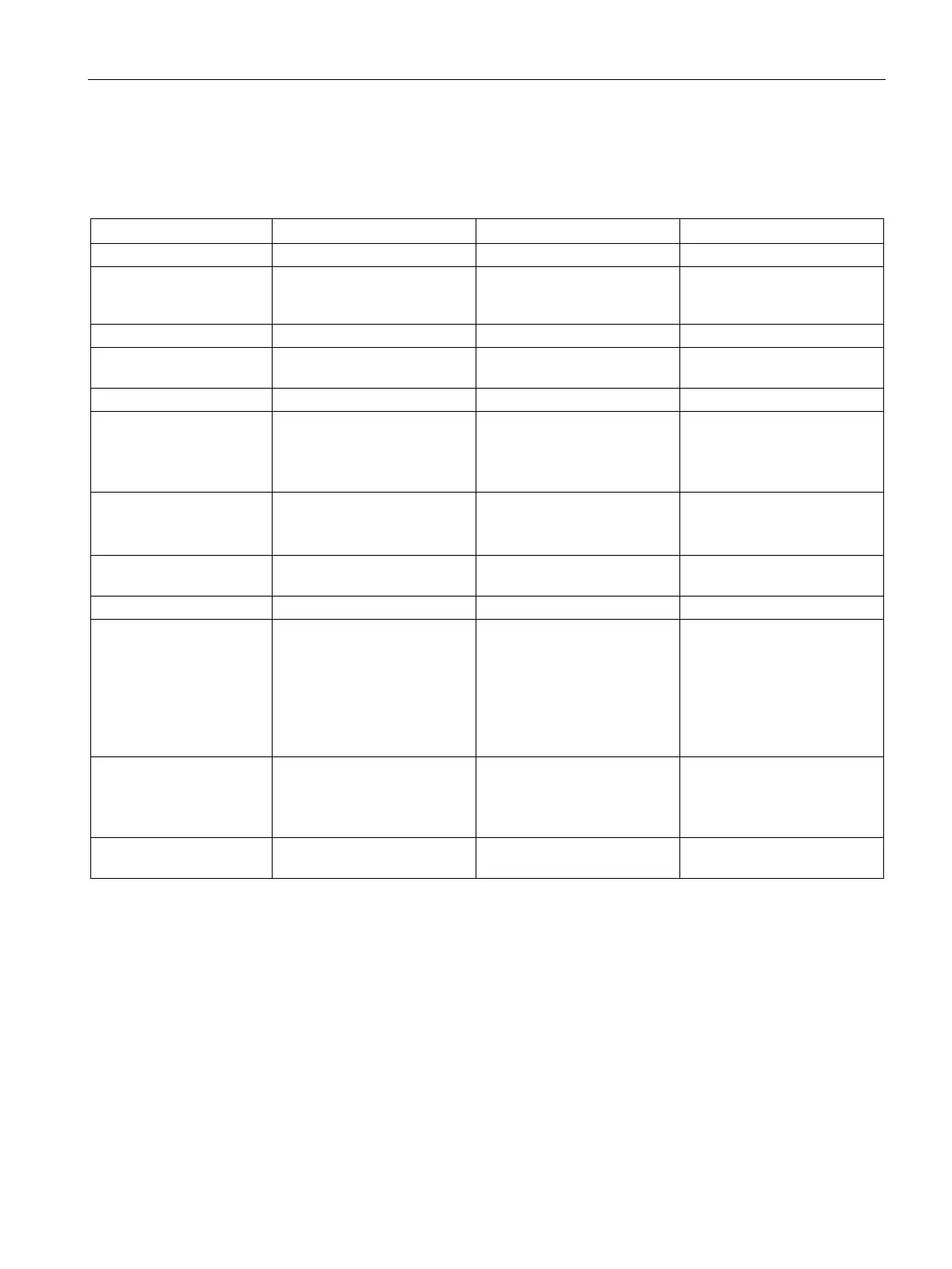
Table A- 15 Digital inputs
Type SinkSource (IEC Type 1 sink,
except I0.0 to I0.3, I0.6 to
Sink/Source (IEC Type 1
sink)
Sink/Source (IEC Type 1
sink)
Continuous permissible
30 V DC, max. 30 V DC, max. 30 V DC, max.
Logic 1 signal (min.) I0.0 to I0.3, I0.6 to I0.7: 4 V
DC at 8 mA
Other inputs: 15 V DC at 2.5
15 V DC at 2.5 mA 15 V DC at 2.5 mA
Logic 0 signal (max.) I0.0 to I0.3, I0.6 to I0.7: 1 V
DC at 1 mA
Other inputs: 5 V DC at 1 mA
5 V DC at 1 mA 5 V DC at 1 mA
Isolation (field side to
500 V AC for 1 minute 500 V AC for 1 minute 500 V AC for 1 minute
Filter times Individually selectable on
each channel (points I0.0 to
I1.3):
μs: 0.2, 0.4, 0.8, 1.6, 3.2, 6.4,
12.8
ms: 0.2, 0.4, 0.8, 1.6, 3.2, 6.4,
Individually selectable on
each channel (points I0.0 to
I1.3):
μs: 0.2, 0.4, 0.8, 1.6, 3.2, 6.4,
12.8
ms: 0.2, 0.4, 0.8, 1.6, 3.2, 6.4,
Individually selectable on
each channel (points I0.0 to
I1.3):
μs: 0.2, 0.4, 0.8, 1.6, 3.2, 6.4,
12.8
ms: 0.2, 0.4, 0.8, 1.6, 3.2, 6.4,
HSC clock input rates
(max.)
(Logic 1 Level = 15 to 26
V DC)
Single phase: 4 HSCs at 200
kHz; 2 HSCs at 30 kHz
A/B phase: 2 HSCs at 100
Single phase: 4 HSCs at 200
kHz; 2 HSCs at 30 kHz
A/B phase: 2 HSCs at 100
Single phase: 4 HSCs at 100
kHz
A/B phase: 2 HSCs at 50 kHz
Number of inputs on
12 12 12

 Loading...


