Installation
3.3 Installation and removal procedures
S7-200 SMART
58 System Manual, V2.3, 07/2017, A5E03822230-AF
Installing and removing an expansion module
Install expansion modules separately after the CPU has been installed. The CPU models
CPU CR20s, CPU CR30s, CPU CR40s, and CPU CR60s do not support the use of
expansion modules or signal boards.
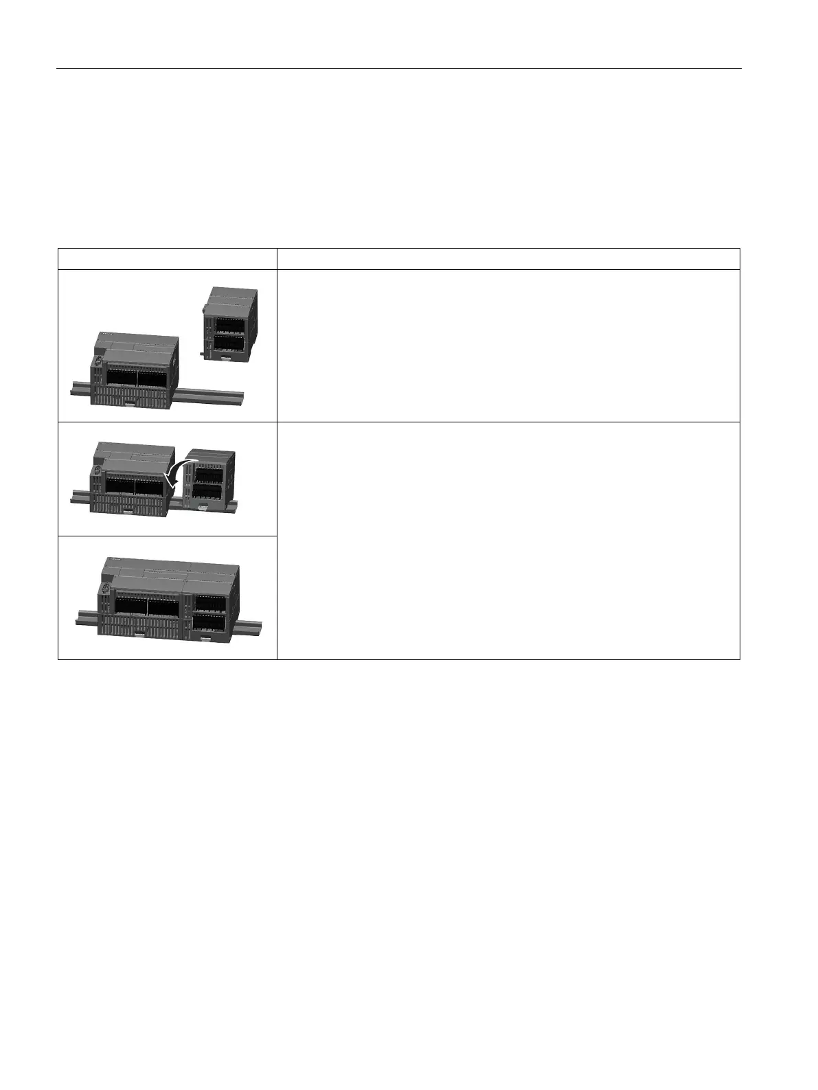
Table 3- 7 Installing an expansion module
Follow the steps below to install an expansion module:
1. Ensure that the CPU and all S7-200 SMART equipment are disconnected from
electrical power.
2. Remove the cover for the I/O bus connector from the right side of the CPU.
3. Insert a screwdriver into the slot above the cover.
4. Gently pry the cover out at its top and remove the cover. Retain the cover for
reuse.
Connect the expansion module to the CPU.
1. Pull out the bottom DIN rail clip to allow the expansion module to fit over the
rail.
2. Position the expansion module to the right of the CPU.
3. Hook the expansion module over the top of the DIN rail.
4. Slide the expansion module to the left until the I/O connector fully engages the
connector on the right of the CPU and push the bottom clip in to latch the ex-
pansion module onto the rail.

 Loading...


