Installation
3.3 Installation and removal procedures
S7-200 SMART
60 System Manual, V2.3, 07/2017, A5E03822230-AF
Installing and removing the expansion cable
The S7-200 SMART expansion cable provides additional flexibility in configuring the layout
of your S7-200 SMART system. Only one expansion cable is allowed per CPU system. You
install the expansion cable either between the CPU and the first EM, or between any two
EMs.
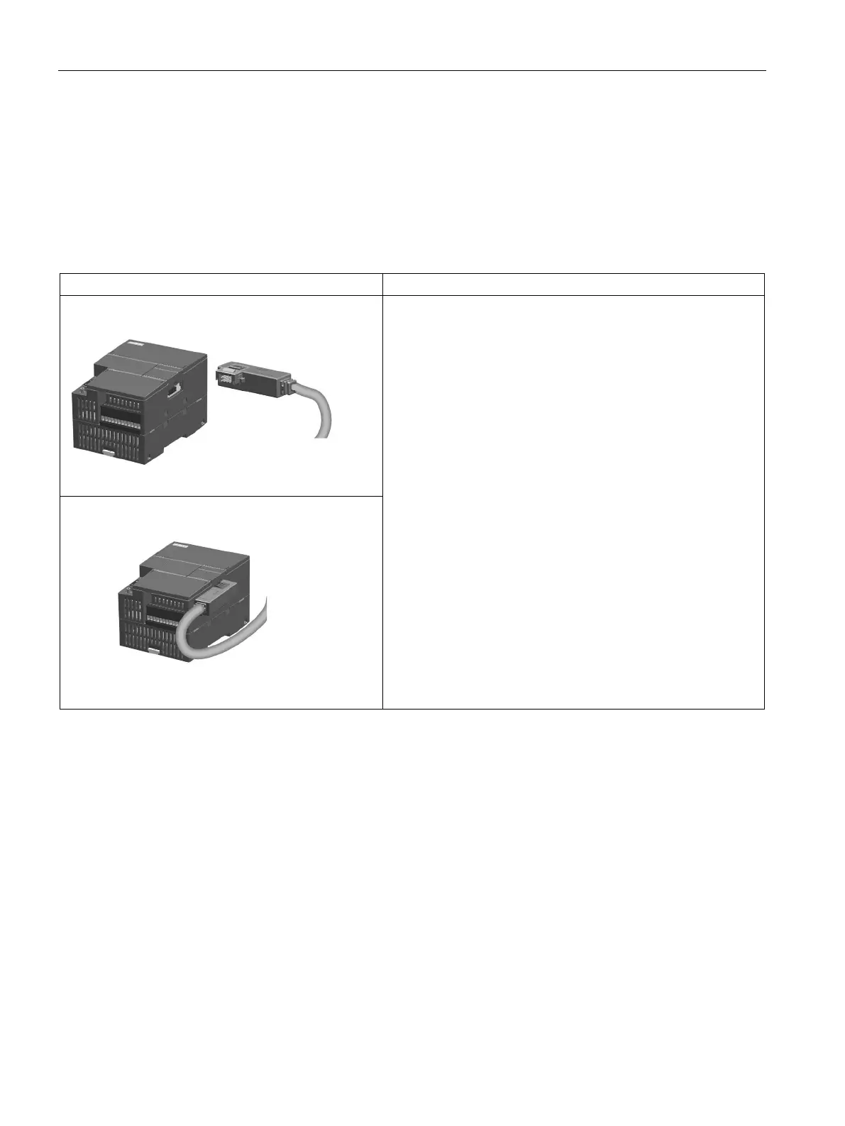
Table 3- 9 Installing and removing the male connector of the expansion cable
To install the male connector:
1. Ensure that the CPU and all S7-200 SMART equipment are
disconnected from electrical power.
2. Push the male connector into the bus connector on the right
side of the expansion module or CPU.
3. The male connector is locked in place when it is fully seeded.
To remove the male connector:
1. Ensure that the CPU and all S7-200 SMART equipment are
disconnected from electrical power.
2. Use your thumb to press down the latch on the top of the
male connector to release it from the expansion module or
CPU.
3. Remove the male connector from the expansion module or
CPU by pulling it straight out.

 Loading...


