PLC device configuration
6.1 Configuring the operation of the PLC system
S7-200 SMART
142 System Manual, V2.3, 07/2017, A5E03822230-AF
By default, the CPU has no defined retentive memory areas, but you can configure the
retentive ranges:
● The S7-200 SMART CPU models CPU SR20, CPU ST20, CPU SR30, CPU ST30, CPU
SR40, CPU ST40, CPU SR60, and CPU ST60 have a maximum of 10 Kbytes of retentive
memory.
● The S7-200 SMART CPU models CPU CR20s, CPU CR30s, CPU CR40s, and CPU
CR60s have a maximum of 2 Kbytes of retentive memory.
Data retention after CPU power interruption
The CPU performs the following actions regarding retentive memory at power down and
power up:
●
The CPU saves the memory ranges designated as retentive to permanent memory.
●
The CPU first clears V, M, C, and T memory, copies any initial values from the data block
to V memory, and then copies the saved retentive values from permanent memory to
RAM.
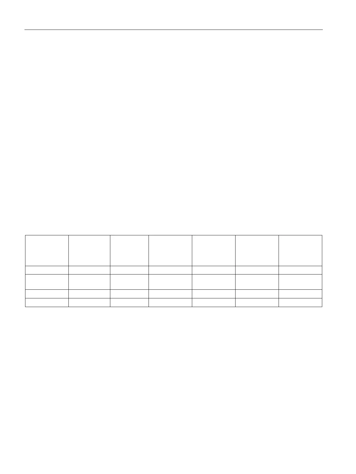
S7-200 SMART CPU memory addresses for retentive ranges
CPU CR20s
CPU CR30s
CPU CR40s
CPU CR60s
T Timers T0-T31,
T64-T95
T0-T31,
T64-T95
T0-T31,
T64-T95
T0-T31,
T64-T95
T0-T31,
T64-T95
M Flag bits MB0-MB31 MB0-MB31 MB0-MB31 MB0-MB31 MB0-MB31

 Loading...


