Program instructions
7.5 Convert
S7-200 SMART
System Manual, V2.3, 07/2017, A5E03822230-AF
241
Converting number values to the ASCII character representation (ITA, DTA, and RTA)
ASCII character output number format:
● Positive values are written to the output buffer without a sign.
● Negative values are written to the output buffer with a leading minus sign (-).
● Leading zeros to the left of the decimal point (except the digit adjacent to the decimal
point) are suppressed.
● Values are right-justified in the output buffer.
● Real numbers: Values to the right of the decimal point are rounded to fit in the assigned
number of digits to the right of the decimal point.
● Real numbers: The size of the output buffer must be a minimum of three bytes more than
the number of digits to the right of the decimal point.
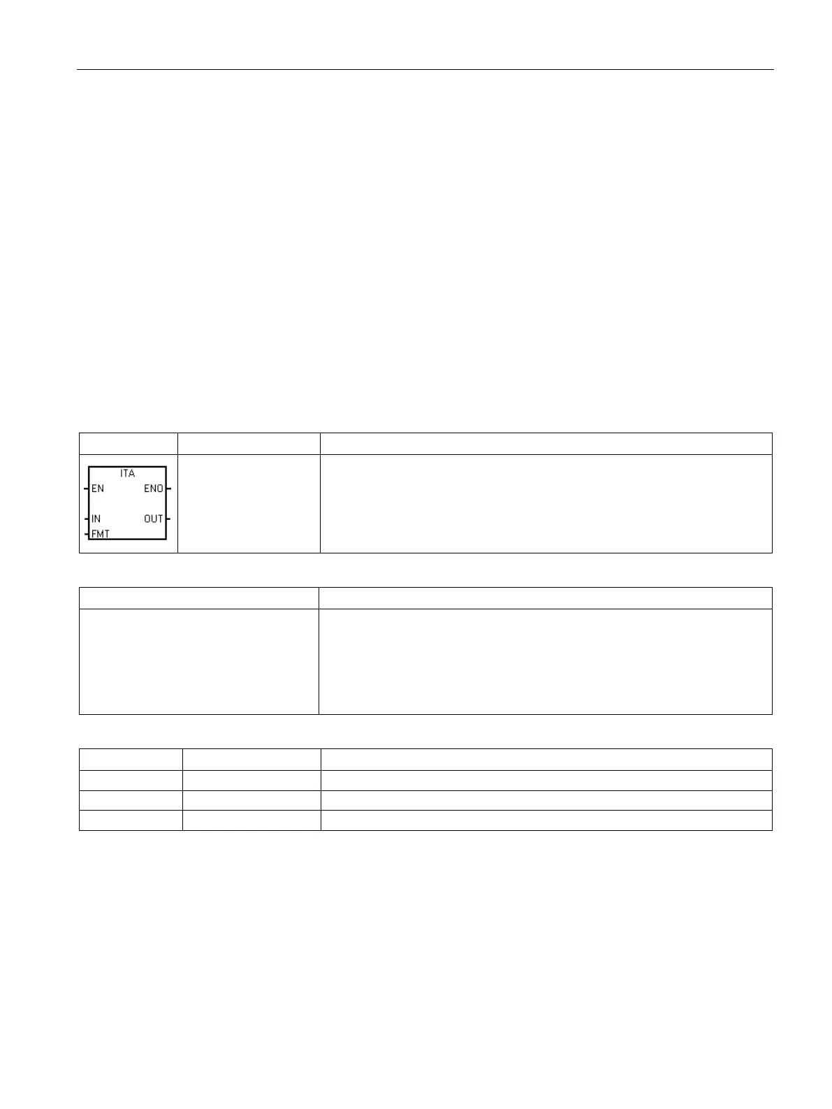
The Integer to ASCII instruction converts the integer value IN to an array of
ASCII characters. The format parameter FMT assigns the conversion precision
to the right of the decimal, and whether the decimal point is to be shown as a
comma or a period. The resulting conversion is placed in 8 consecutive bytes
beginning with the address assigned by OUT.
Non-fatal error conditions with ENO = 0
• 0006H Indirect address
• 0091H Operand out of range
• FMT bit is not zero for 4 most signifi-
cant bits of the FMT byte
• nnn > 5
None
IW, QW, VW, MW, SMW, SW, T, C, LW, AC, AIW, *VD, *LD, *AC, Constant
IB, QB, VB, MB, SMB, SB, LB, AC, *VD, *LD, *AC, Constant
IB, QB, VB, MB, SMB, SB, LB, *VD, *LD, *AC
The size of the output buffer is always 8 bytes. The number of digits to the right of the
decimal point in the output buffer is assigned by the nnn field. The valid range of the nnn
field is 0 to 5. If you assign 0 digits to the right of the decimal point, then the value is
converted with no decimal point. For values of nnn greater than 5, the output buffer is filled
with ASCII space characters. The c bit specifies the use of either a comma (c=1) or a
decimal point (c=0) as the separator between whole number and fraction. The most
significant 4 bits must always be zero.
The following figure shows examples of values that are formatted using a decimal point (c=0)
with three digits to the right of the decimal point (nnn=011).

 Loading...


