Libraries
9.3 Modbus RTU library
S7-200 SMART
System Manual, V2.3, 07/2017, A5E03822230-AF
485
Parameter
assigns the number of data elements to read or write in this request. The
Count is the number of bits for the bit data types, and the number of words for the word data
types.
● Address 0xxxx Count is the number of bits to read or write
● Address 1xxxx Count is the number of bits to read
● Address 3xxxx Count is the number of input register words to read
● Address 4xxxx or 4yyyyy Count is the number of holding register words to read or write
The MBUS_MSG / MB_MSG2 instruction reads or writes a maximum of 120 words or 1920
bits (240 bytes of data). The actual limit on the value of Count depends on the limits in the
Modbus slave device.
The parameter
is an indirect address pointer that points to the V memory in the CPU
for the data associated with the read or write request. For a read request, set the DataPtr to
the first CPU memory location used to store the data read from the Modbus slave. For a
write request, set DataPtr to point to the first CPU memory location of the data to be sent to
the Modbus slave.
The program passes the DataPtr value to MBUS_MSG / MB_MSG2 as an indirect address
pointer. For example, if the data to be written to a Modbus slave device starts at address
VW200 in the CPU, the value for the DataPtr would be &VB200 (address of VB200).
Pointers must always be a type VB even if they point to word data.
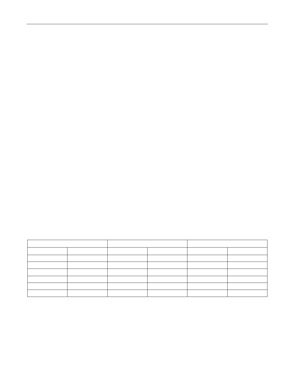
Holding registers (address 4xxxx or 4yyyyy) and input registers (address 3xxxx) are word
values (2 bytes or 16 bits). CPU words are formatted the same as Modbus registers. The
lower numbered V memory address is the most significant byte of the register. The higher
numbered V memory address is the least significant byte of the register. The table below
shows how the CPU byte and word addressing corresponds to the Modbus register format.
Table 9- 7 Modbus Holding Register
Modbus holding register address
VB202 56 VW202 56 78 40002 56 78

 Loading...


