Technical specifications
A.2 S7-200 SMART CPUs
S7-200 SMART
System Manual, V2.3, 07/2017, A5E03822230-AF
715
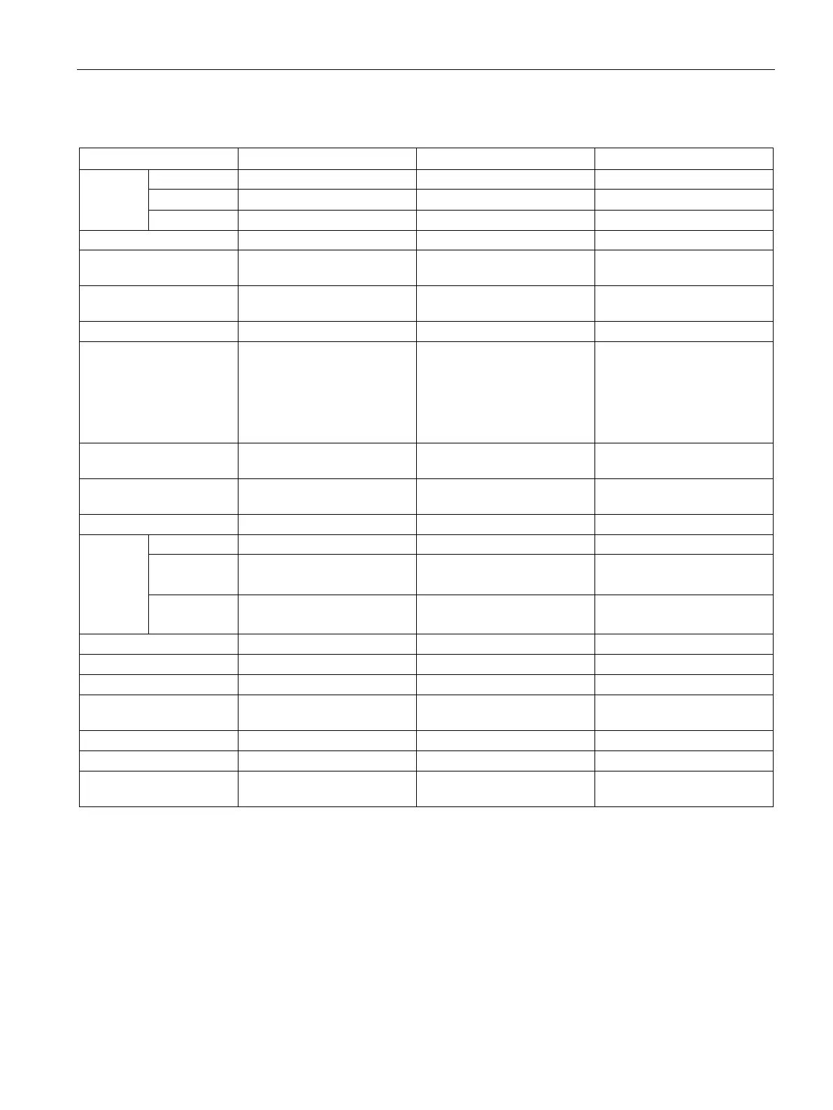
Table A- 54 CPU features
User
memory
User data (V) 20 Kbytes 20 Kbytes 8 Kbytes
1
1
1
On-board digital I/O 36 inputs/24 outputs 36 inputs/24 outputs 36 inputs/24 outputs
Process image 256 bits of inputs (I) / 256 bits
256 bits of inputs (I) / 256 bits
256 bits of inputs (I) / 256 bits
Analog image 56 words of inputs (AI) / 56
56 words of inputs (AI) / 56
Not available
Temporary (local) memory
(L)
64 bytes in the main program
and 64 bytes in each subrou-
tine and interrupt routine
60 bytes when programming
in LAD or FBD (STEP 7-
Micro/WIN reserves 4 bytes)
64 bytes in the main program
and 64 bytes in each subrou-
tine and interrupt routine
60 bytes when programming
in LAD or FBD (STEP 7-
Micro/WIN reserves 4 bytes)
64 bytes in the main program
and 64 bytes in each subrou-
tine and interrupt routine
60 bytes when programming
in LAD or FBD (STEP 7-
Micro/WIN reserves 4 bytes)
Sequential control relays
256 bits 256 bits 256 bits
Expansion modules ex-
6 max. 6 max. Not available
High-
speed
counters
Single phase 4 at 200 kHz
2 at 30 kHz
4 at 200 kHz
2 at 30 kHz
4 at 100 kHz
A/B phase 2 at 100 kHz
2 at 100 kHz
2 at 50 kHz
2
Edge interrupts 4 rising and 4 falling (6 and 6
with optional signal board)
4 rising and 4 falling (6 and 6
with optional signal board)
4 rising and 4 falling
microSDHC card (optional)
microSDHC card (optional)
Real time clock retention
7 days typ./6 days min. at 25
7 days typ./6 days min. at 25
Not available
You can configure a
reas of V memory, M memory, C memory (current values) and portions of T memory (current values
on retentive timers) to be retentive, up to the specified maximum amount.
The specified maximum pulse frequency is possible only for CPU models with transistor outputs. Pulse output operation
is not recommended for CPU models with relay outputs.

 Loading...


