Configuration
3.20 Configuring data points
Configuration - DNP3
124 Configuration Manual, 11/2018, C79000-G8976-C508-01
Set limit value 'low' / Set limit value 'high'
Requirements for the function
● Configuration of the threshold trigger for this data point
● PLC tag in the bit memory operand area or data area
The analog value data point must be linked to a PLC tag in the memory or data area
(data block).
For PLC tags for analog input modules (input operand area) limit value configuration is
not possible. With these analog values the limit values of the following table are used
automatically.
The configuration of limit values is pointless for measured values that have already been
preprocessed on the CPU.
In these two input boxes, you can set a limit value in the direction of the start of the
measuring range or in the direction of the end of the measuring range.
You can also evaluate the limit values, for example as the start or end of the measuring
range.
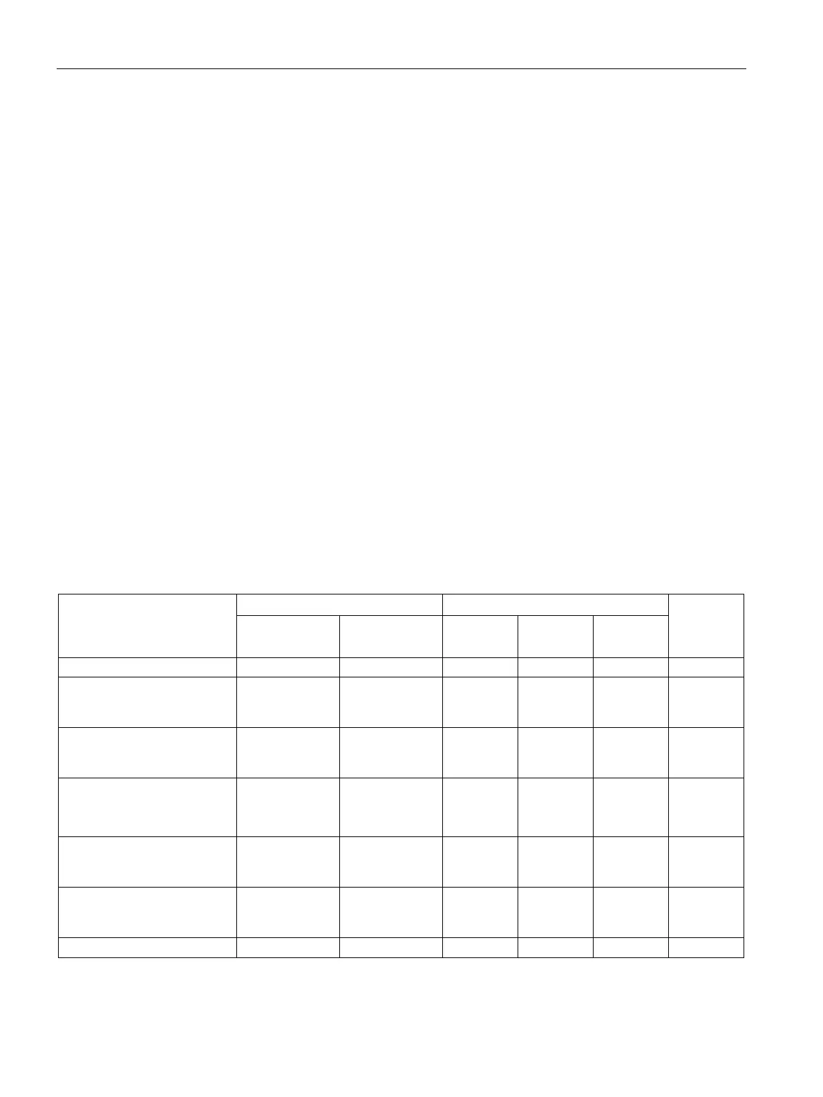
Configuration of the limit value
The limit value is configured as a whole decimal number. The range of values is based on
the range of values of the raw value of analog input modules.
Please note: The entry of the value 0 (zero) is interpreted as a deactivated limit value.
Value of the 16-bit PLC variable *
Overrange 32511
...
7EFF
...
23.515
...
23.515
...
22.810
...
117.593
...
Nominal range
(unipolar / life zero)
27648
...
6C00
...
20
...
20
...
100
...
Nominal range (bipolar) 27648 ...
0
6C00 ...
0000
20 ...
0
100 ...
0
Underrange
(unipolar / life zero)
-1
...
FFFF
...
-0.001
...
3.999
...
-0.004
...
Underrange (bipolar) -27649
...
93FF
...
-20.001
...
-100.004
...