Configuration
3.19 Telecontrol connections
Configuration - DNP3
92 Configuration Manual, 11/2018, C79000-G8976-C508-01
The "Connection path" table supports you in checking the connection paths. For every
configured connection, the detailed connection path is shown here.
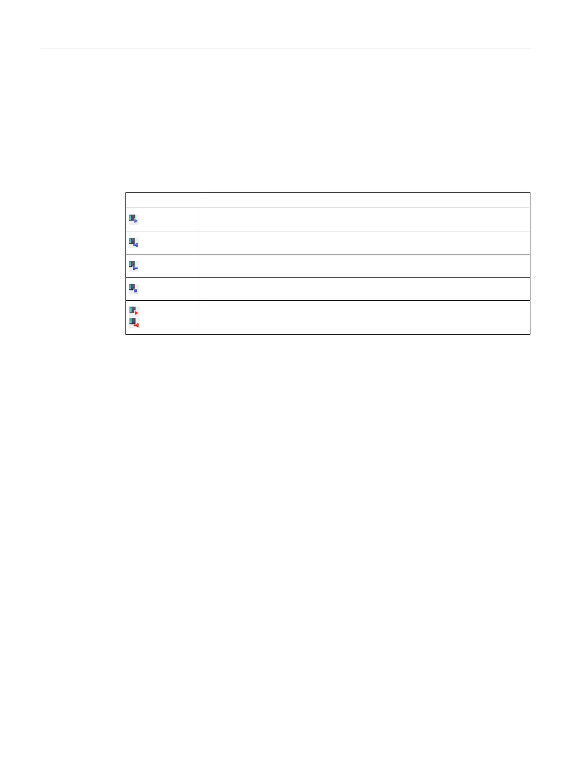
A station symbol with an identifier for the connection point is displayed in the "Position"
column. The color of the identifier indicates the validity of the connection point:
● Blue: Valid connection point
● Red: Invalid connection point
Starting point
Node-input
Node-output
Endpoint
Examples of invalid connection points
Parameters of the connection table
Here, you configure the parameters of the connection table for each connection segment.
You can find the description of the parameters in the section Connection table (Page 92).
The "Properties" tab, which shows additional parameters for each connection segment, is
displayed below the connection table.
"Properties" tab of the connections
In the parameter groups, you can check the connection segment, correct it if necessary and
configure additional properties.
You can find a description of the parameter groups in the section Parameters of the DNP3
connections (Page 97).
The first row below the table header contains a filter function with which you can restrict the
selection of configurable subscribers and connection options. Using filters reduces the
number of combination possibilities and increases the clarity.
Once you have created some connection segments, enable the filter by entering a recurring
name or partial name in the filter cell. The cell is given a colored background, see figure.