Accessories
A.5 LTOP overvoltage protection modules
TIM DNP3
System Manual, 12/2015, C79000-G8976-C253-04
329
Note
The protection elements in the OPM (O
vervoltage
rotection
odule) undergo high stress
during discharge processes and progressively
deteriorate. It is therefore recommended that
you replace the OPMs approximately once a year. To be on the safe side, in regions with
frequent thunderstorms this period should be reduced to approximately 6 months.
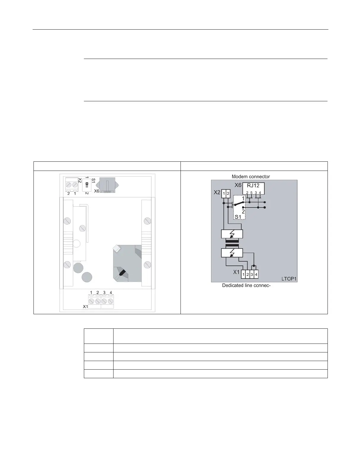
Structure of the LTOP variants
The housing contains either one LTOP unit (= LTOP 1) or two LTOP units (= LTOP 2). The
following figures show the design of both LTOP variants with their connectors and
configuration switches.
X1 Dedicated line (screw terminals 1, 2, 5, 6)
Chassis (screw terminals 3, 4)
Modem attachment 2-wire over screw terminals
Modem attachment 4-wire over screw terminals
Modem attachment 2-wire/4-wire via RJ-12 western plug

 Loading...


