LEDs and connectors
3.1 TIM 3V-IE DNP3
TIM DNP3
54 System Manual, 12/2015, C79000-G8976-C253-04
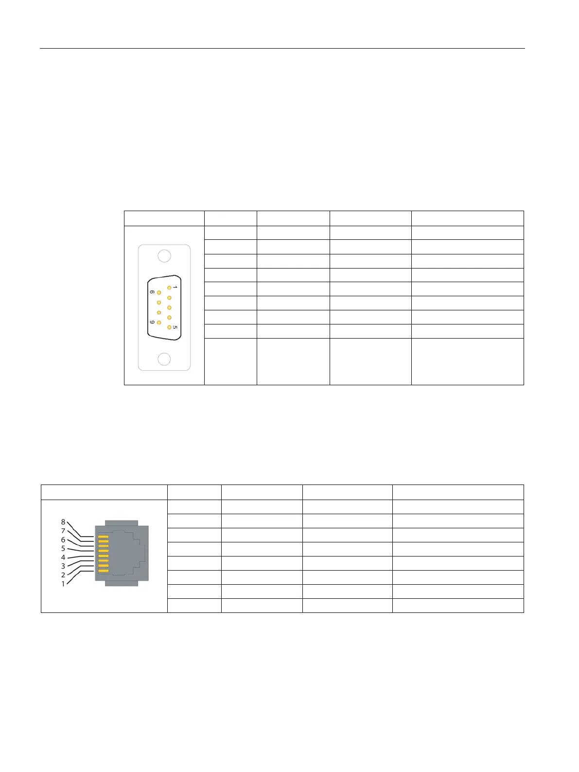
Pinout of the ports
RS-232 interface
The connector for the RS-232 port is designed as a 9-pin D-sub miniature connector (male).
The pinout is shown in the following table. As an RS-232 port, the pinout corresponds to that
of a standardized PC connector.
Table 3- 3 Pinout of the RS-232 port connector for connecting an external modem
2 RXD Input
9 -
The connector of the Ethernet port is designed as an 8-pin RJ-45 Western jack. The pinout is
shown in the following table.
Table 3- 4 Pinout of the RJ-45 Western jack for the Ethernet port

 Loading...


