7
7.2 Fault Recorders
67Digital Fault Recorder, SIMEAS R-PMU, Manual
E50417-H1076-C360-A5, Release 10.2012
7.2.1.2 Trigger Functions
Several trigger limits and recording times can be parameterized for the Transient Analog
Recorder. The input signals are analyzed according to the trigger conditions and start the fault
recording if the trigger condition is met. The duration of the fault record depends on the
parameterized recording times and can be prolonged by a repeated limit value violation
(retriggering) within the recording time. The recording time is limited to a maximum of 30 s plus
1 s prefault time for each TAR fault record.
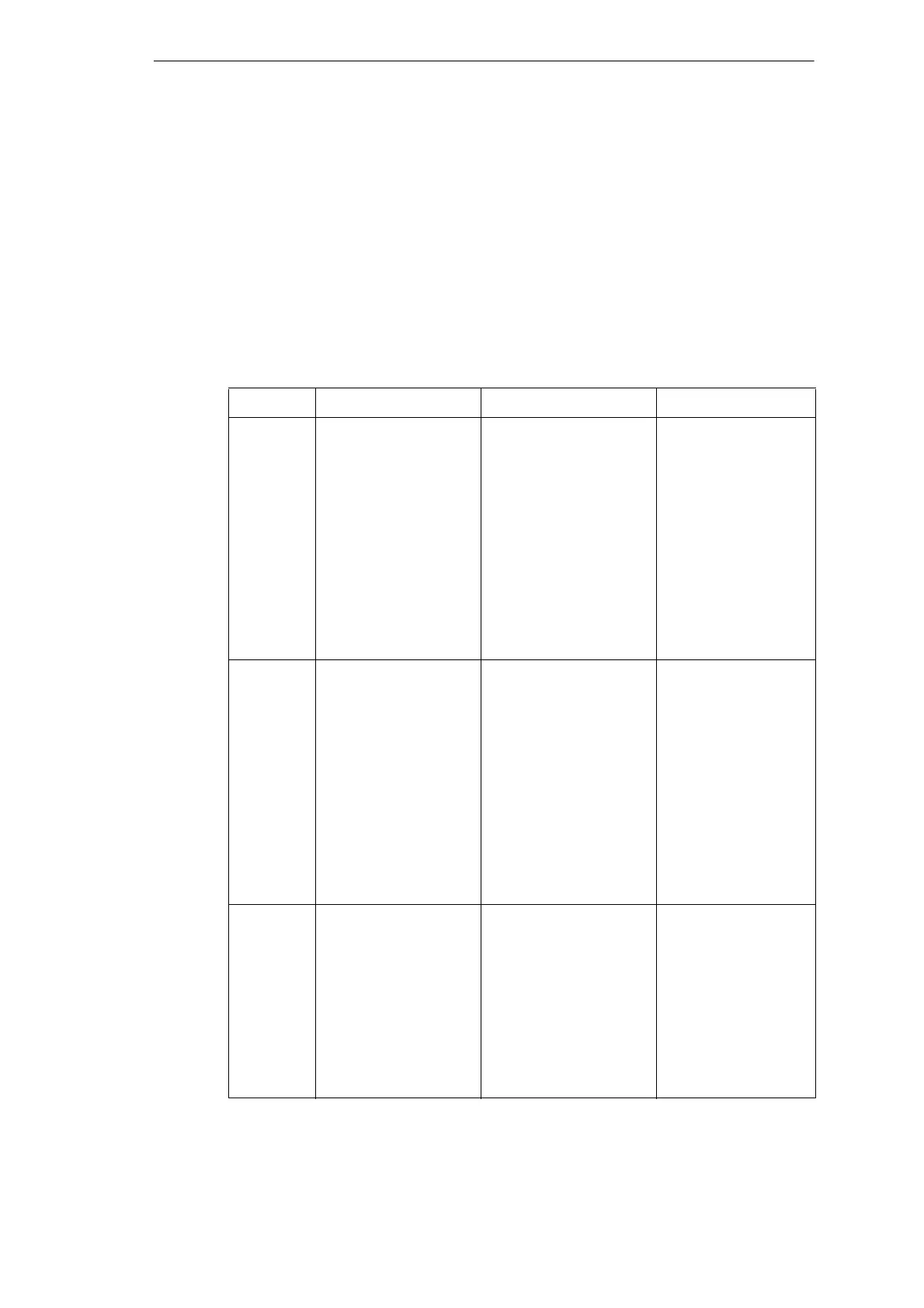
The tables 7-11 and 7-12 show the values that the Transient Analog Recorder can trigger to,
depending on the data acquisition modules (the powers in the CDAU column are applicable only
for coupled CDAUs).
Note: dt is always 2 nominal cycles with the TAR.
Table 7-11 Trigger values of the VCDAU, VDAU and CDAU depending on the input
connection (the length of dt is two periods for the TAR)
VCDAU VDAU CDAU
Star
connection
V
L1
, V
L2
, V
L3
, V
N
dV
L1
/dt, dV
L2
/dt
dV
L3
/dt, dV
N
/dt
V
1
, V
2
, V
0
I
L1
, I
L2
, I
L3
, I
N
dI
L1
/dt, dI
L2
/dt
dI
L3
/dt, dI
N
/dt
I
1
, I
2
, I
0
B
1
to B
16
V
L1-1
, V
L2-1
, V
L3-1
, V
N4
dV
L1-1
/dt, dV
L2-1
/dt
dV
L3-1
/dt, dV
N4
/dt
V
1-1
, V
2-1
, V
0-1
V
L1-2
, V
L2-2
, V
L3-2
, V
N8
dV
L1-2
/dt, dV
L2-2
/dt
dV
L3-2
/dt, dV
N8
/dt
V
1-2
, V
2-2
, V
0-2
B
1
to B
16
I
L1-1
, I
L2-1
, I
L3-1
, I
N4
dI
L1-1
/dt, dI
L2-1
/dt
dI
L3-1
/dt, dI
N4
/dt
I
1-1
, I
2-1
, I
0-1
I
L1-2
, I
L2-2
, I
L3-2
, I
N8
dI
L1-2
/dt, dI
L2-2
/dt
dI
L3-2
/dt, dI
N8
/dt
I
1-2
, I
2-2
B
1
to B
16
Delta
connection
V
L12
, V
L23
, V
L31
, V
4
dV
L12
/dt, dV
L23
/dt
dV
L31
/dt, dV
4
/dt
V
1
, V
2
I
L1
, I
L2
, I
L3
, I
4
dI
L1
/dt, dI
L2
/dt
dI
L3
/dt, dI
4
/dt
I
1
, I
2
B
1
to B
16
V
L12-1
, V
L23-1
, V
L31-1
, V
4
dV
L12-1
/dt, dV
L23-1
/dt
dV
L31-1
/dt, dV
4
/dt
V
1-1
, V
2-1
V
L12-2
, V
L23-2
, V
L31-2
, V
8
dV
L12-2
/dt, dV
L23-2
/dt
dV
L31-2
/dt, dV
8
/dt
V
1-2
, V
2-2
B
1
to B
16
I
L1-1
, I
L2-1
, I
L3-1
, I
4
dI
L1-1
/dt, dI
L2-1
/dt
dI
L3-1
/dt, dI
4
/dt
I
1-1
, I
2-1
, I
0-1
I
L1-2
, I
2L-2
, I
L3-2
, I
8
dI
L1-2
/dt, dI
L2-2
/dt
dI
L3-2
/dt, dI
8
/dt
I
1-2
, I
2-2
B
1
to B
16
Monophase V
L1
, V
L2
, V
L3
, V
L4
dV
L1
/dt, dV
L2
/dt
dV
L3
/dt, dV
L4
/dt
I
L1
, I
L2
, I
L3
, I
L4
dI
L1
/dt, dI
L2
/dt
dI
L3
/dt, dI
L4
/dt
B
1
to B
16
V
L1
, V
L2
, V
L3
, V
L4
dV
L1
/dt, dV
L2
/dt
dV
L3
/dt, dV
L4
/dt
V
L5
, V
L6
, V
L7
, V
L8
dV
L5
/dt, dV
L6
/dt
dV
L7
/dt, dV
L8
/dt
B
1
to B
16
I
L1
, I
L2
, I
L3
, I
L4
dI
L1
/dt, dI
L2
/dt
dI
L3
/dt, dI
L4
/dt
I
L5
, I
L6
, I
L7
, I
L8
dI
L5
/dt, dI
L6
/dt
dI
L7
/dt, dI
L8
/dt
B
1
to B
16
 Loading...


