12
12.11 Slot Description
160 Digital Fault Recorder, SIMEAS R-PMU, Manual
E50417-H1076-C360-A5, Release 10.2012
12.11.5 DC Channels
The DC channels tab is only provided for DDAU modules. This tab is used to parameterize
operational data and information regarding the display of values in OSCOP P.
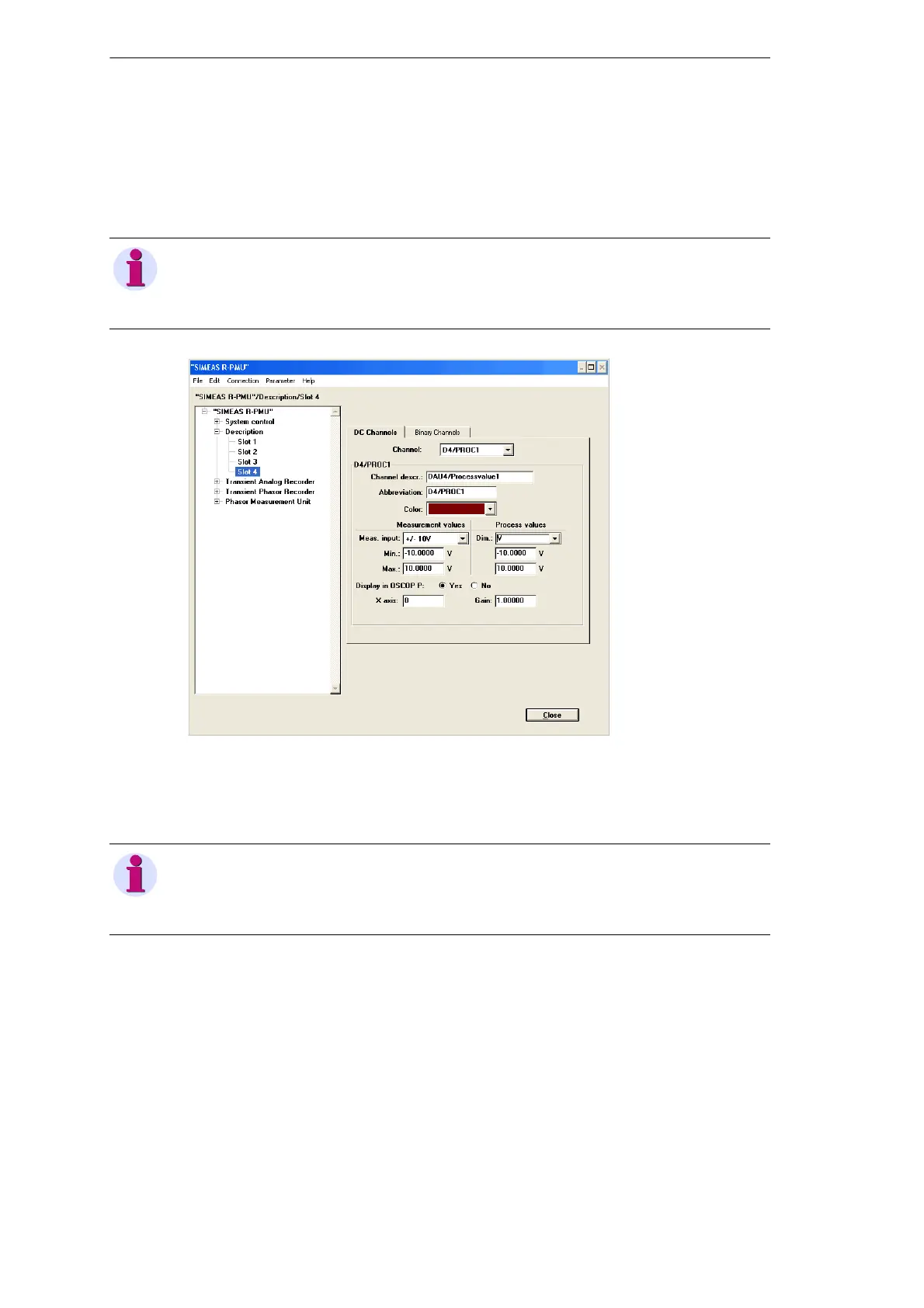
Figure 12-25 DC channels tab
Select one of the analog channels from the drop-down menu of the Channel box.
Enter the Channel descr. and Abbreviation and select a Color.
Select the secondary signal variable that is provided on the input terminals of the DDAU from
the drop-down menu Meas. input under Measurement values.
Enter the minimum and maximum of the secondary signal variable into the Min. and Max.
boxes.
Use the drop-down menu Dim. under Process values to select the dimension of the
measured value to be displayed as a y-axis label in the OSCOP P Evaluate module, or enter
a string consisting of maximum six characters. Enter the minimum and maximum of the
converted process variable into the Min. and Max. boxes.
Note
DDAUs are manufactured for input ranges of DC ±1 V, DC ±10 V or DC ±20 mA. Please check
the type of DDAUs used and make sure you parameterize the input signal variables according
to their intended use.
Note
For DC channels, a mapping for measured values to process signals can be parameterized.
Example: The measurement range DC 0 V to DC +10 V is mapped to the process signals -50 °C
to +100 °C.
 Loading...


