5
05.01
5.1 Closed–loop control with digital setpoint interface
5-110
© Siemens AG 2008 All Rights Reserved
SIMODRIVE 611 Configuration Manual (PJU) – 05/2008 Edition
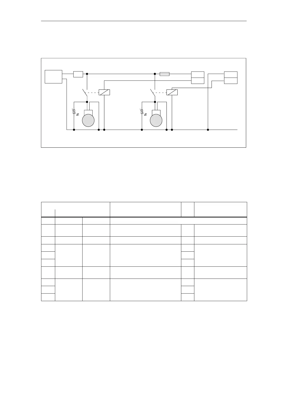
T. BE2
Relays
to
control
the motor
holding brake
M 1
3
24 V
Motor with
motor
holding brake
0 V
Term. P24 Term. M24
SITOP
P24
X431
BI1
M24
X432
BI2
M 2
3
<10 m
Power
supply,
e.g. SITOP
power
Term. BE1
Fuse
1)
1) Overvoltage circuitry, e.g. varistor
K1 K2
High Standard/Performance
Relays
to
control
the motor
holding brake
Axis 1 Axis 2
1)
Safety circuit
Fig. 5-3 Circuit example: Connecting a motor holding brake to a High Standard/High Performance control board
Table 5-6 BERO input X461/X462
Pin
Function Type
Technical specifications
No. Designation
1)
X461 X462 Type: 9–pin D–sub socket connector
1 FRP FRP Internal enable voltage
(jumpered with terminal 9)
O +24 V
2 BERO1 BERO2 BERO input I +13 ... 30 V
3 Reserved,
Reserved,
–
4
do not use do not use
–
5 –
6 FRM FRM Internal enable voltage
(jumpered with terminal 19)
O 0 V
7 Reserved,
Reserved,
–
8
do not use do not use
–
9 –
1) I: Input; O: Output
Holding brake
connection
BERO input
X461/X462
5 Control Units 05.08