6
05.01
6.2 Function overview and settings
6-154
© Siemens AG 2008 All Rights Reserved
SIMODRIVE 611 Configuration Manual (PJU) -- 05/2008 Edition
6.2 Function overview and settings
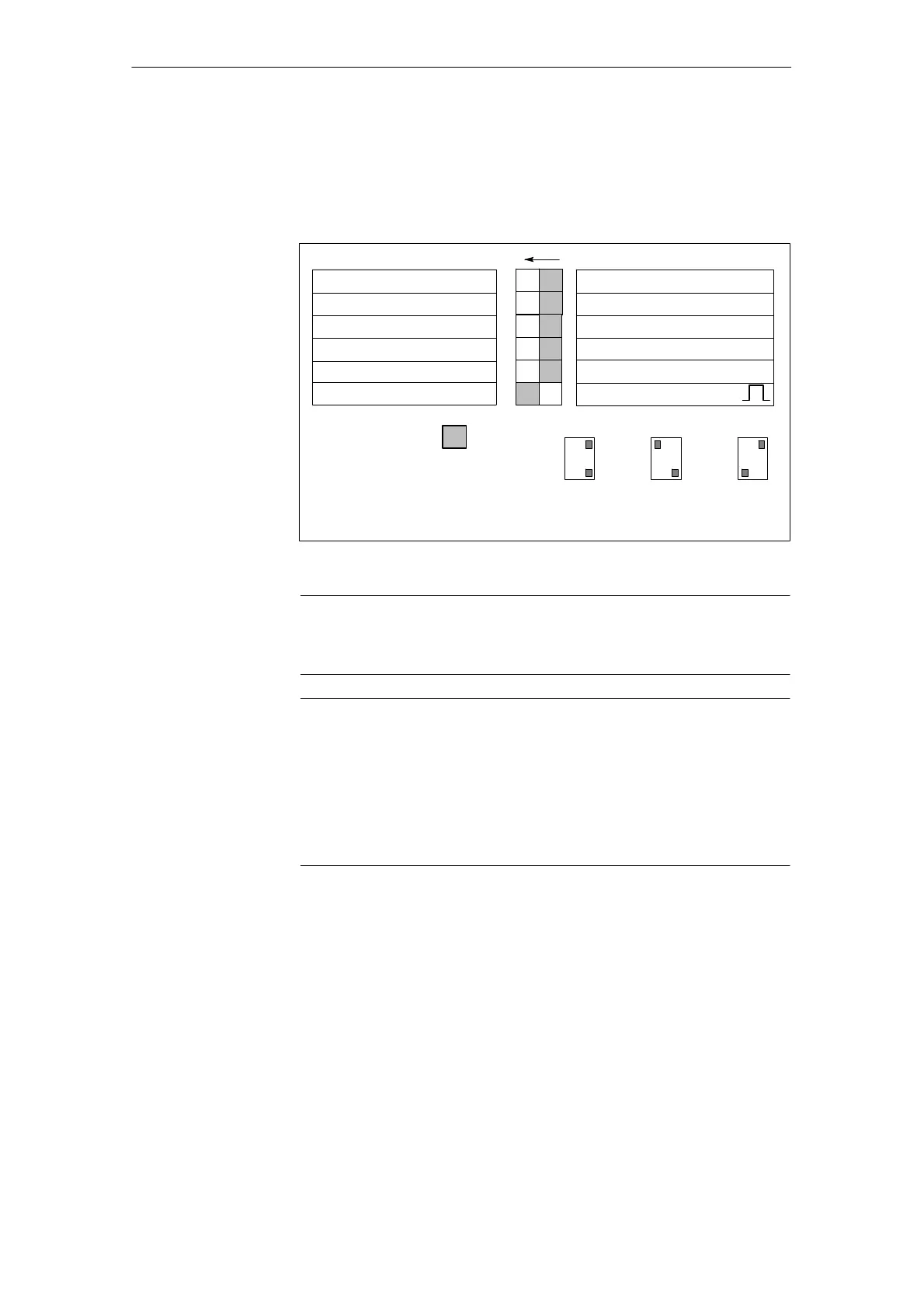
A s witch S1 is provided on the upper side of the NE and monitoring module that
is used to set the following functions (for UI 5 kW on the front side):
ON: OFF:
V
line
= 415 V10% V
DC link
= 625 V
1)
Error message
Regenerative feedback into the
line supply off
V
line
= 400 V10% V
DC link
= 600 V
1)
Regenerative feedback into the
line supply on
1
2
3
4
V
line
= 480 V
+
6% -- 10%
2)
Ready signal
S1
Controlled infeed off
Controlled infeed
5
6
Standard, refer to switch S1.1
Sinusoidal current operation µ
Squarewave current operation
Standard setting
ON 1
4
.
.
3--ph. 400 V AC
ON 1
4
.
.
3--ph. 415 V AC
ON 1
4
.
.
3--ph. 480 V AC
S1.1
S1.4
(on the line side)
(on the line side)
1) Only possible for I/R modules -- for all
NE modules, the monitoring thresholds are increased (2.5%).
2) For S1.4 = ON, S1.1, S1.3 and S1.6 have no effect.
Fig. 6-5 DIL switch S1
Note
For a configuration 480 V S1.4= ON, only controlled regenerative feedback is
realized, independent of the position of S1.5.
Notice
For I/R modules, sinusoidal current mode is the initial setting.
For operation with filters that are not listed in Table 6-1, the mode must be
changed to squarewave current mode in order to protect the filter from thermal
overload.
Before powering up or down using the main switch or a line contactor, terminal
63 (pulse enable) and/or terminal 48 (start terminal, contactor control) must be
de--energized!
OFF: I/R module U
line
= 400 V 10%; V
DC link
= 600 V 2.5%
UI module V
line
= 400 V 10%; V
DC link
=V
line
¯ 1.35
Monitoring thresholds: (I/R, UI, monitoring modules)
PR on = 644 V; PR off = 618 V 2.5%
V
DC link
≥ 695 V 2.5%
ON: I/R module V
line
= 415 V 10%; V
DC link
= 625 V 2.5%
UI module V
line
= 415 V (440 V) 10%; V
DC link
=V
line
¯ 1.35
Monitoring thresholds: (I/R, UI, monitoring modules)
PR on = 670 V 2.5%; PR off = 640 V 2.5%
V
DC link
≥ 710 V 2.5%
PR = Pulsed resistor
General
information
Switch S1.1
6 Infee
Mo
ule
11.0505.08