3
05.01
3.5 Overview, position sensing
3-79
© Siemens AG 2008 All Rights Reserved
SIMODRIVE 611 Configuration Manual (PJU) – 05/2008 Edition
3.5 Overview, position sensing
Table 3-3 Assignment, motor measuring systems to control unit
Drive control unit, High Performance (FD mode)
Drive control unit, High Performance (MSD mode)
Drive control unit, High Standard (FD mode)
Drive control unit, High Standard (MSD mode)
Drive control unit 611 universal HRS resolver
Drive control unit 611 universal HRS– 1 Vpp voltage signals
Motor type
Encoder system
Yes 1FK
Servo motor
Resolver
Yes Yes Yes 1FT/1FK
Servo motor
Incremental encoder 1 Vpp
Yes Yes Yes 1FT/1FK
Servo motor
Multiturn absolute encoders
Yes Yes Yes 1FN
Linear motor
Incremental encoder (Hall sensor box) 1 Vpp
Absolute encoder
Yes Yes Yes 1PH4/6/7
Main spindle motor
Incremental encoder 1 Vpp
Yes Yes Yes 1FE1/1PH2/1PM/2SP1
Main spindle motor
Incremental encoder (hollow–shaft encoder) 1 Vpp
(toothed wheel or magnetic)
Yes Yes Yes 1FW
Built–in torque motor
Incremental encoder 1 Vpp
Absolute encoder
Yes Yes Yes Yes 1LA standard motor Encoderless (sensorless)
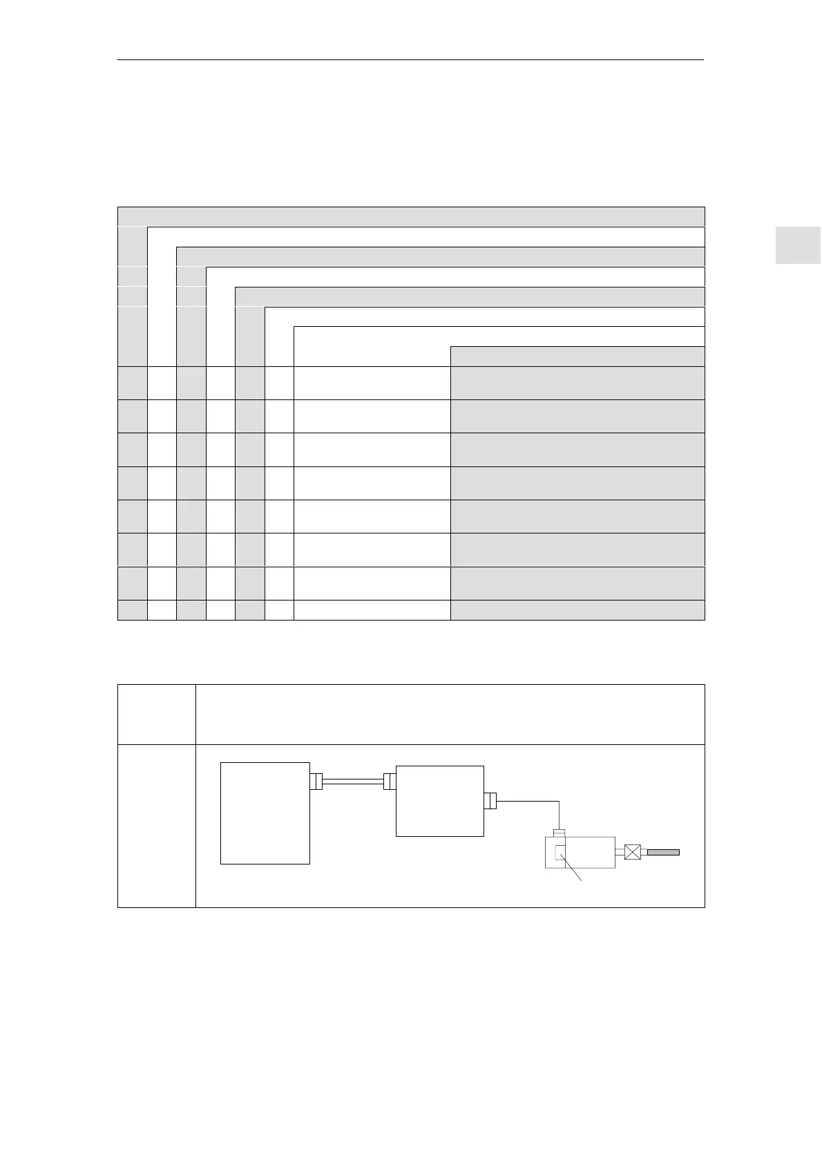
Table 3-4 Indirect position (motor rotor position) and motor speed sensing digital controls
Version of
the
control
board
Indirect position (motor rotor position) and motor speed
sensing digital controls
Drive
control
High Perfor–
mance/
High Stan-
dard
1FT6
1FK
1PH
1PM
SIMODRIVE
drive module
SINUMERIK
840D powerline
drive bus
Drive bus
Incremental
l 50 m
3 Motor Selection, Position/S
eed Sensin
11.05