3
05.01
3.5 Overview, position sensing
3-80
© Siemens AG 2008 All Rights Reserved
SIMODRIVE 611 Configuration Manual (PJU) – 05/2008 Edition
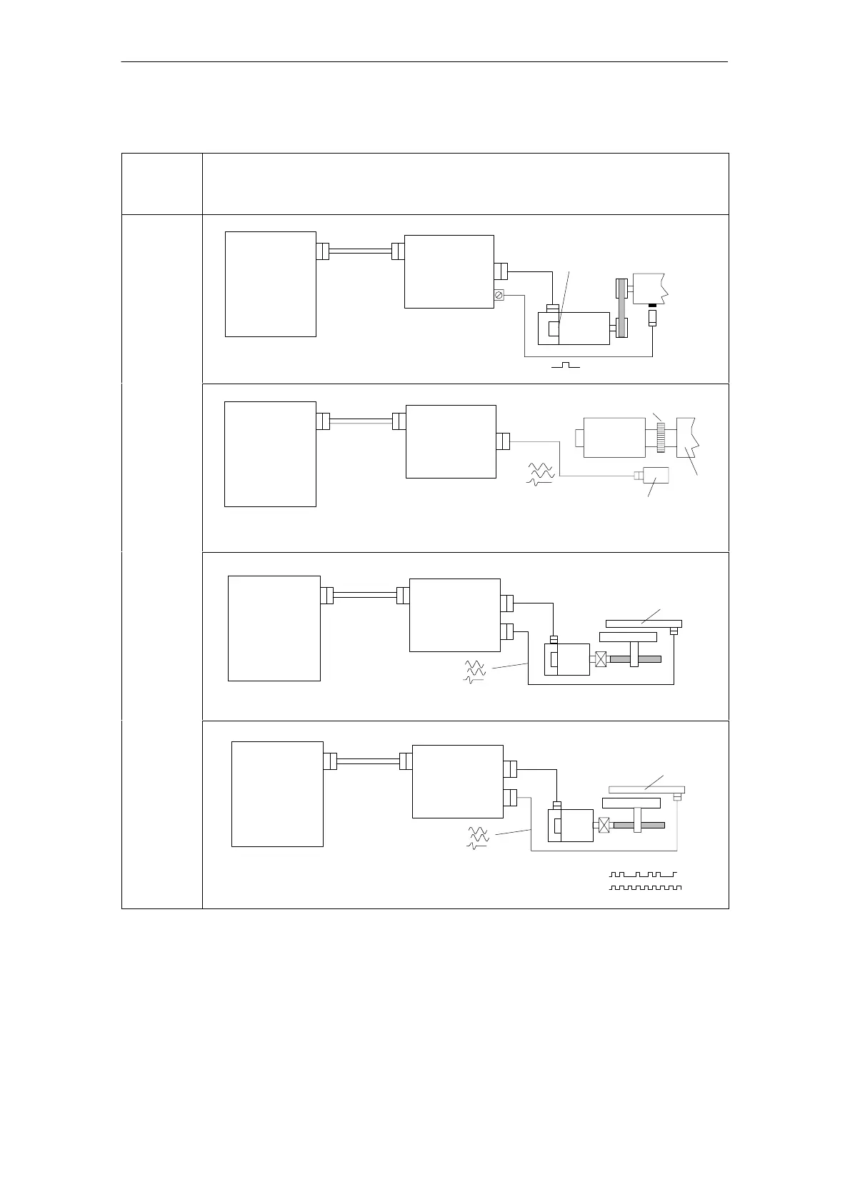
Table 3-5 Direct position sensing, digital control
Version of
the
control
board
Direct position sensing, digital controls
1PH4/6/7
1FE
Incremental
BERO
1)
BERO function
not released for FD
l 50 m
SIMODRIVE
drive module
SINUMERIK
840D powerline
drive bus
Drive bus
Drive
control
SIMODRIVE
drive module
SINUMERIK
840D powerline
drive bus
Drive bus
Toothed wheel
1PH2
1FE
Spindle
Sensor head
l 50 m
Voltage signals
High Perfor–
mance/
High Stan-
dard
SIMODRIVE
drive module
SINUMERIK
840D powerline
drive bus
Drive bus
1FT6
Linear
2)
measuring
system
incremental
l 50 m
l 50 m
Voltage signals
1FK
SIMODRIVE
drive module
SINUMERIK
840D powerline
drive bus
Drive bus
1FT6
l 50 m
l 50 m
1FK
Linear measuring
system
incremental and
absolute
Voltage signals
and EnDat interface
Data
clock
1) The absolute accuracy for so–called synchronization with a BERO depends on the following:
– the switching time of the BERO
– the hysteresis of the BERO
– the signal edge gradient (rate–of–rise) of the BERO signal (depending on the direction of rotation) and the switching
thresholds in the drive; high > 13 V, low < 5 V
– the search speed and the signal runtimes in the evaluation electronics
2) Distancecoded reference marks can be evaluated
3 Motor Selection, Position/S
eed Sensin
11.05