8
05.01
8.5 Start inhibit in the drive modules/safe standstill
8-261
© Siemens AG 2008 All Rights Reserved
SIMODRIVE 611 Configuration Manual (PJU) -- 05/2008 Edition
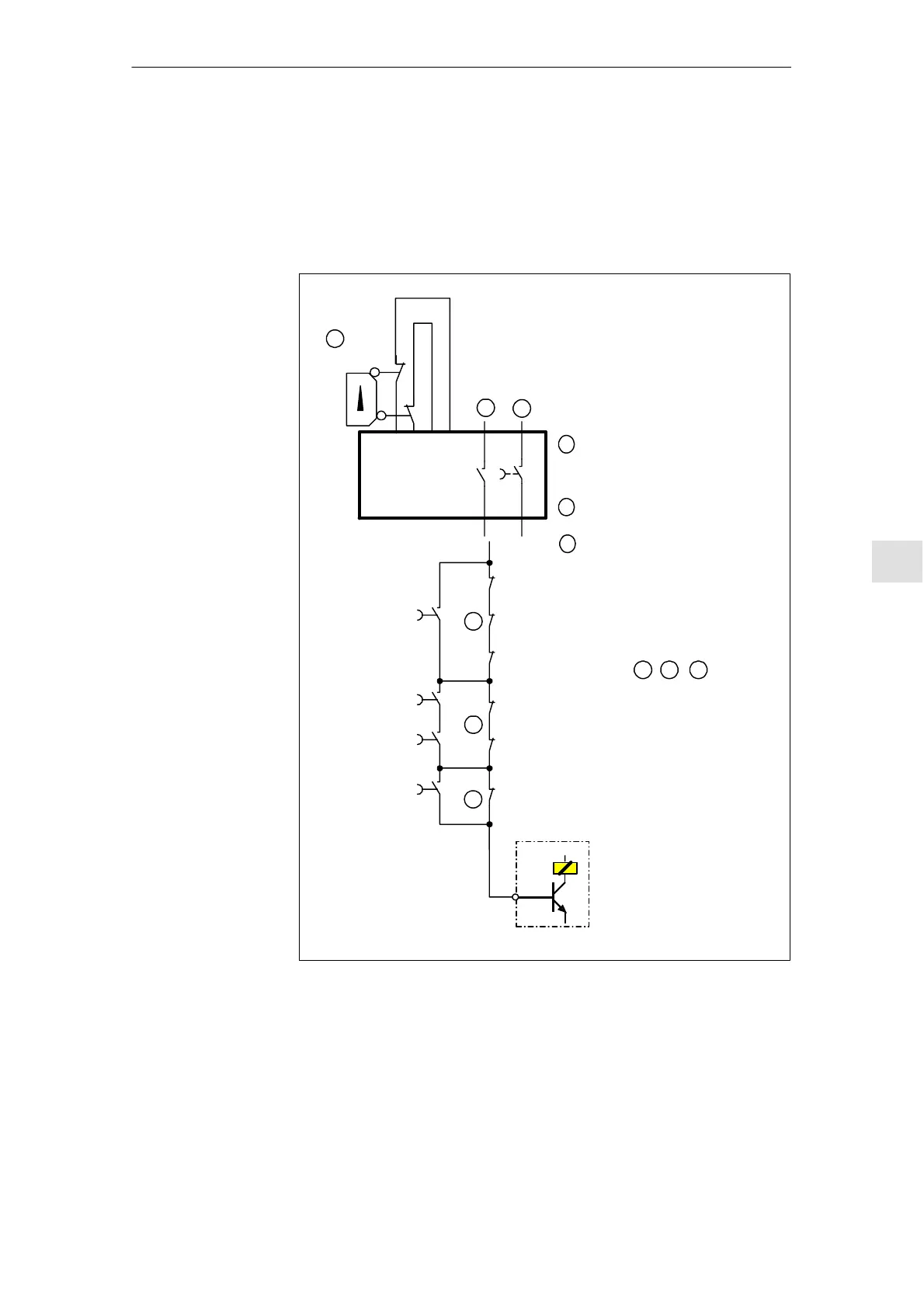
8.5.7 Example, ”safe standstill” for several drive groups
The concept of the ”safe standstill” function with higher--level main contactor as
shown in Fig. 8-12 is implemented on an electrical injection molding machine.
Enable
c
b
a
For a protective device with tumbler mechanism:
An enable signal is issued, if n=0, and
simultaneously inhibit the pulses via
the control unit
Instantaneous contact at the
start inhibit, terminal 663
Delayed contact at the
interlocking logic
b
c
a
2
1
3
Main contactor
AS1
AS2
AS1
AS2
AS1
AS2
AS1
AS2
AS1
AS2
AS1
AS2
Protective door A
Protective door A
Protective door B
Protective door B
Drive 1.1
Drive 1.2
Drive 1.3
Drive 2.1
Drive 2.2
Drive 3.1
Line supply infeed NE
48
Start
EN+
1 2 3
Moving protective device
Fig. 8-12 Example, ”safe standstill” function with several drive groups
The machine comprises three functional drive groups. The feedback signal con-
tacts of each control unit AS1/AS2 within a drive group are c onnected in series.
Every drive group is secured using a moving protective device. Interdependen-
cies according to Table 8-4 apply between the drive groups and moving protec-
tive devices.
Function
Im
o
n
C
cu
Info
m
on02.03