6
05.01
6.3 Technical data
6-162
© Siemens AG 2008 All Rights Reserved
SIMODRIVE 611 Configuration Manual (PJU) – 05/2008 Edition
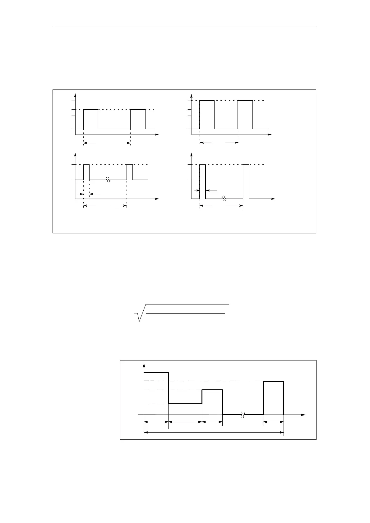
6.3.2 Permissible duty cycles/derating
t
P
P
max
P
n
P
s6
0.4 P
n
4 min
10 min
t
P
P
max
P
n
P
s6
0.4 P
n
10 s
60 s
t
P
P
max
P
n
0.2 s
10 s
t
P
P
n
4 s
10 s
F P
n
F: For all NE modules up to Pn 80 kW, F = 1.6 applies
For Pn = 120 kW, F = 1.4 applies (F = factor)
Peak power load duty cycle without pre–load
Peak power load duty cycle with pre–load
Peak power load duty cycle with pre–load
S6 load cycle with pre–load condition
Fig. 6-7 Nominal load duty cycles for NE modules
The effective load must be determined over a load period/cycle and this must
be set to the ratio for the rated power of the module. The resulting weighting
factor B must not exceed the factors of the associated time interval T indicated
in Table 6-7. Note that the maximum P
max
must not be exceeded at any time
and the derating factor, depending on the pulse frequency and/or installation
altitude, must be taken into account!
As a rule of thumb, the following applies for block-type load duty cycles:
B =
P
1
2
t
1
+ P
2
2
t
2
+...+ P
k
2
t
k
T Total duration of the load duty cycle
P
n
Rated power of the I/R module
P
1
...P
k
Magnitude of the required power
t
1
...t
k
Duration of the corresponding power
B Evaluation factor for the load duty cycle according to Table 6-7
T P
n
2
P
t
1
t
t
2
t
3
t
k
T
P
1
P
k
P
3
P
2
Fig. 6-8 Explanation of the rule of thumb for block–type load duty cycles
Nominal load duty
cycles for NE
modules
Calculation of
maximum
permissible line
infeed load
6 Infeed Modules 11.0502.07