1
05.01
1.2 Engineering steps
1-28
© Siemens AG 2008 All Rights Reserved
SIMODRIVE 611 Configuration Manual (PJU) – 05/2008 Edition
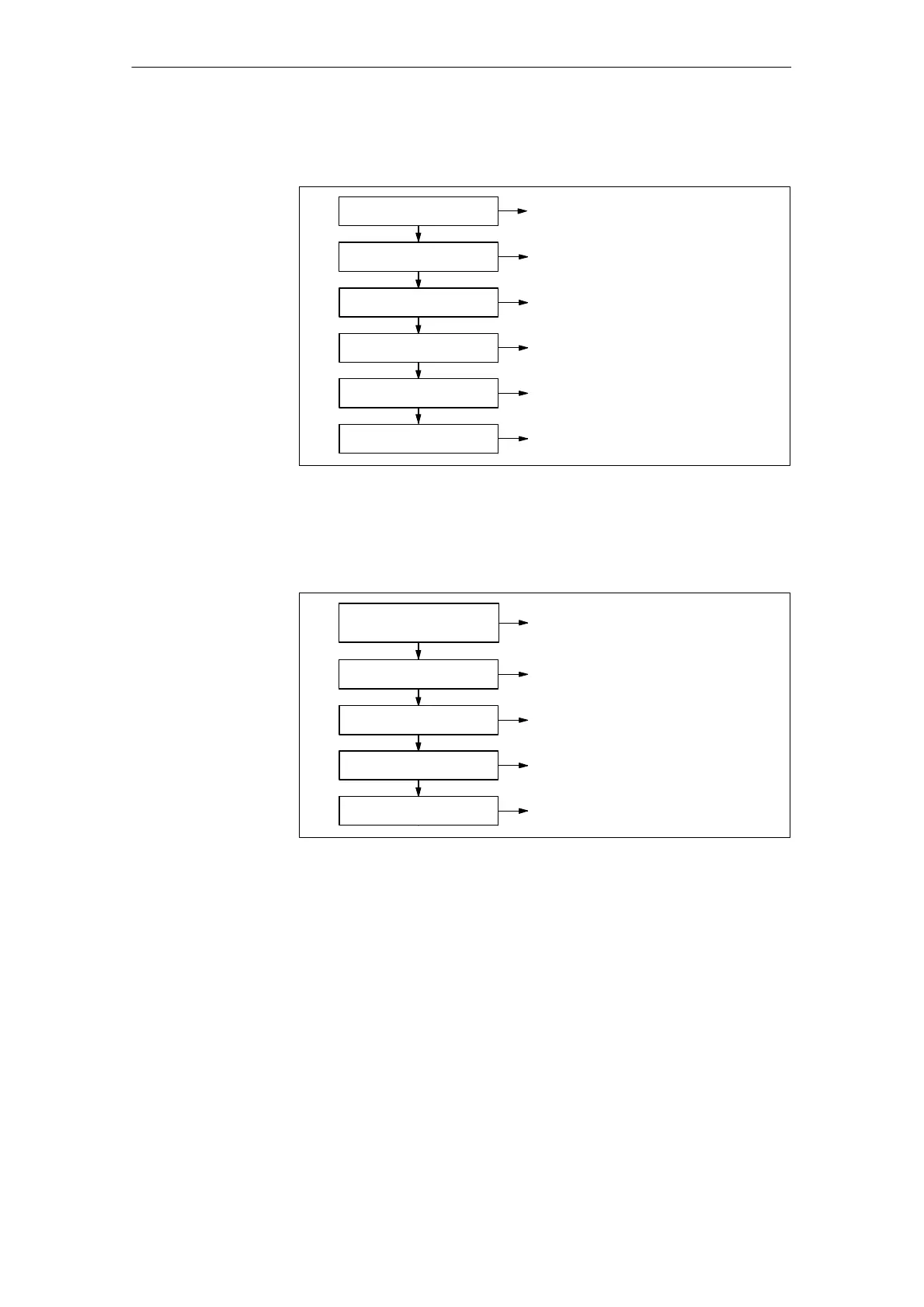
Selecting components
Motor selection See Chapter 3
See Chapter 3
Position sensing
See Chapter 4
Power modules
See Chapter 5
Control units
See Chapter 6
Infeed modules
See Chapter 7
Line supply connection
Fig. 1-4 Selecting components
Connecting–up
Important
circuit information
See Chapter 8
See Chapter 9Cabinet design and EMC
See Chapter 5Block diagrams
See Chapter 10
Connection diagrams
Dimension drawings
See Chapter 12
Fig. 1-5 Connecting–up
Cables, cable protection and switching devices must be selected carefully tak-
ing into account the relevant regulations, standards and the requirements of the
location where the system is installed.
Reference: /NCZ/ Catalog, Connecting System
and System Components
Reference: /NSK/ Catalog, Low Voltage
Switchgear
Phase 1 when
engineering
Phase 2 when
engineering
Selecting
cables, cable
protection and
switching devices
1 Overview of the Drive S
stem