6
05.01
6.3 Technical data
6-161
© Siemens AG 2008 All Rights Reserved
SIMODRIVE 611 Configuration Manual (PJU) – 05/2008 Edition
6.3.1 Connection conditions for line supply infeed modules
The line supply infeed modules are adapted to the actual line supply conditions
using switches S1.1 and S1.4 (refer to Chapter 6.2).
The converter system is designed for operation connected to grounded TNS
and TNC line supplies (VDE 0100 Part 300). For other line supply types, an
upstream transformer must be used with isolated windings in a YN vector group
on the secondary side (refer to Chapter 7 when dimensioning/selecting this
transformer).
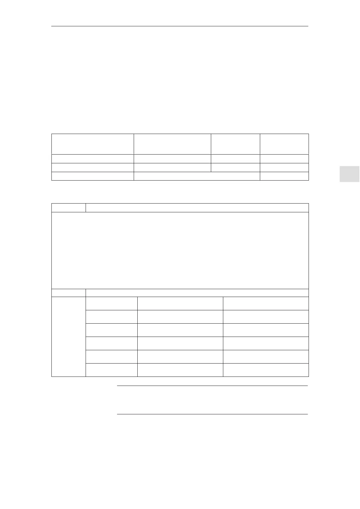
Table 6-5 Supply voltage and frequency
NE modules S1.1, S1.4 = OFF
Vn = 3–ph. 400 V AC
S1.1 = ON
Vn = 3–ph.
415 V AC
S1.4 = ON
Vn = 3–ph.
480 V AC
Supply voltage: U1, V1, W1 3–ph. 360..440 V AC 3–ph. 373..457 V AC 3–ph. 432..509 V AC
With derating to 70% P
n
and P
max.
1)
Minimum 323 ... .360 V 3 AC
Frequency 45...65 Hz 55...65 Hz
1) If the derating performance does not suffice, the next larger line supply infeed module should be used.
Table 6-6 Line supply connection conditions for NE modules
Module Description
The NE modules are designed for symmetrical 3–phase line supplies with grounded neutral point: TN systems. No further
consumers with asymmetric load (single–phase) may be connected for transformers with non–loadable neutral point.
The line supply specifications according to EN 50178 are complied with as a result of the series (upstream) line reactor (for
5 kW and 10 kW UI, these are integrated in the module).
Notice
The described minimum line supply fault level is needed to trigger the fuses in the case of ground fault and short–circuit within
the prescribed time in order to protect the plant and prevent damage and faults at other devices.
An insufficient system fault level (short–circuit power) increases the triggering and also prevents the triggering of the fuses.
This can cause, for example, arcs with the consequent fire of danger.
The required apparent power of the line supply for each NE module is S
n
= P
n
S 1.27. If an infeed is operated by itself on
a matching transformer, the minimum S
K
of 0.73 times the value from the table is permitted.
UI modules Operation on line supplies from S
Kline
/Pn 30
I/R module
Pn I/R module Sinusoidal current operation (S1.6
= ON)
Squarewave current operation
(S1.6 = OFF)
16 kW S
K
line 1.0 MVA
(70 S Pn
I/R
module
in
kW
)
S
K
line 1.5 MVA
(100 S Pn
I/R
module
in
kW
)
36 kW S
K
line 2.5 MVA
(70 S Pn
I/R
module
in
kW
)
S
K
line 3.5 MVA
(100 S Pn
I/R
module
in
kW
)
55 kW S
K
line 4.0 MVA
(70 S Pn
I/R
module
in
kW
)
S
K
line 5.5 MVA
(100 S Pn
I/R
module
in
kW
)
80 kW S
K
line 5.0 MVA
(60 S Pn
I/R
module
in
kW
)
S
K
line 6.5 MVA
(80 S Pn
I/R
module
in
kW
)
120 kW S
K
line 7.0 MVA
(60 S Pn
I/R
module
in
kW
)
S
K
line 9.5 MVA
(80 S Pn
I/R
module
in
kW
)
Note
UL requirement, maximum permitted line supply short–circuit current SCCR
65 kA.
Before powering–up the system for the first time, the cabinet wiring, the motor/
encoder feeder cables and DC link connections must be carefully checked to
ensure that there are no ground faults.
Supply voltage
and
frequency
No ground faults
6 Infeed Modules11.0505.08

 Loading...


