6
05.01
6.6 Monitoring module
6-178
© Siemens AG 2008 All Rights Reserved
SIMODRIVE 611 Configuration Manual (PJU) – 05/2008 Edition
6.6.3 Mode of operation
Parameters critical for operation are monitored in the monitoring module – these
include:
S DC link voltage
S Controller power supply ( 15 V)
S 5 V voltage level
If these parameters are in the permissible operating range, then the internal
prerequisites for the ”Unit ready” signal are available. The module group con-
nected to the monitoring module is enabled as soon as the external enable sig-
nals have been issued via terminals 63 (pulse enable) and 64 (drive enable).
The total signal activates the ”Ready” relay and can be fetched potential–free
using the 74/73.2 and 73.1/72 terminals. The load capability of the contacts is
250 V AC/1 A or 30 V DC/1 A.
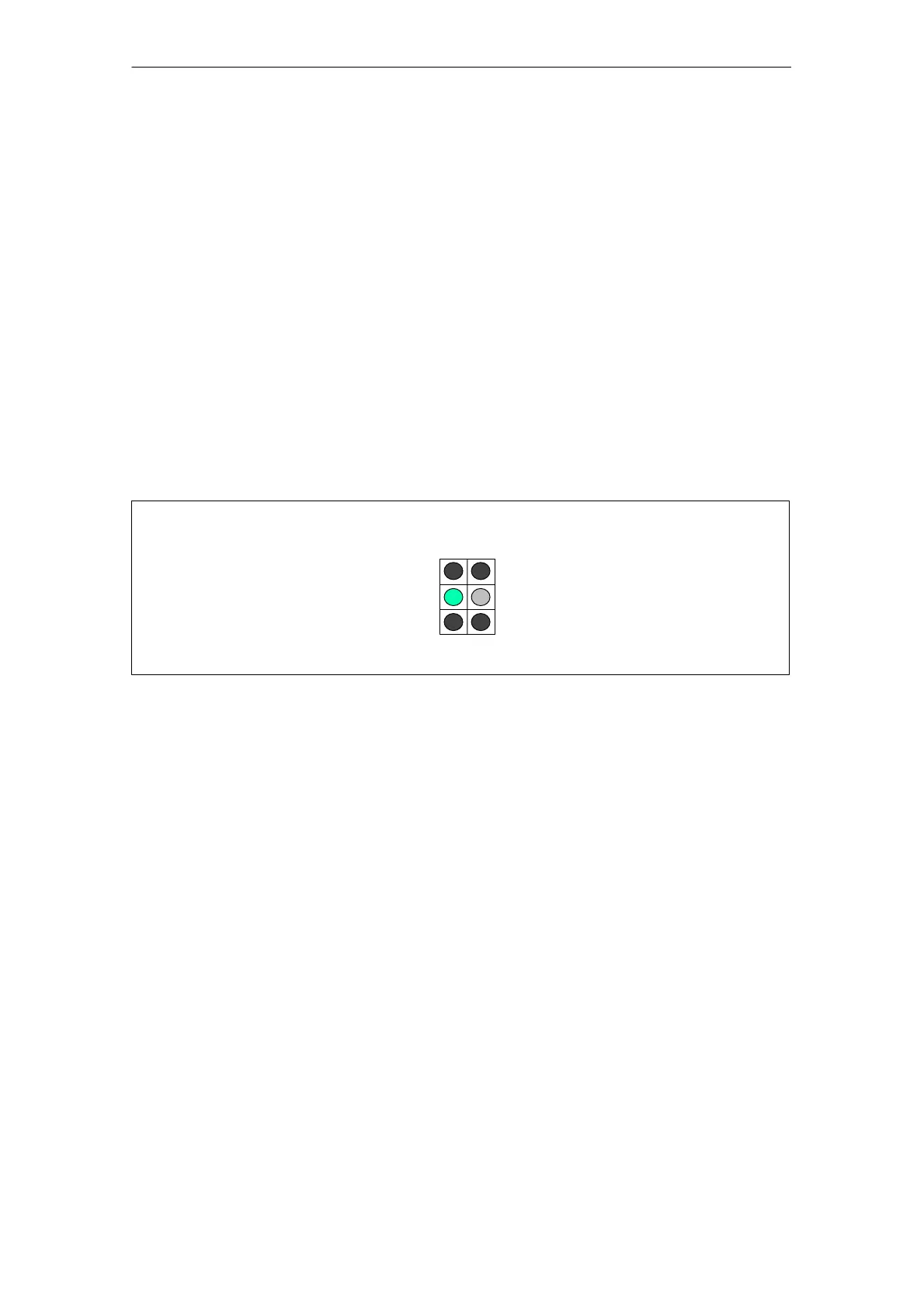
LEDs on the front panel of the monitoring module indicate the signal states of
the monitoring circuits.
red
yellow
red
5 V voltage
level faulted
Unit ready
(DC link
pre–charged)
DC link
overvoltage
Electronics power
supply faulted
Unit not ready,
external enable signals
missing
free
red
green
red
LED display
Fig. 6-13 LED display of the monitoring module
6 Infeed Modules 11.05