4
05.01
4.6 Interfaces and terminals
4-98
© Siemens AG 2008 All Rights Reserved
SIMODRIVE 611 Configuration Manual (PJU) -- 05/2008 Edition
4.6 Interfaces and terminals
4.6.1 Interface overview
Table 4-5 1--axis module
Term.
no.
Designa-
tion
Function
Type
1)
Typ. voltage/limit values Max. cross--section
U2
V2
W2
A1 Motor connection O 3--ph. 430 V AC See Chapter4.6.2
PE Protective conductor
Protective conductor
0V
0V
2screws
P600
M600
DC link
DC link
I/O
I/O
+300 V
--300 V
Busbar
Busbar
Table 4-6 2--axis module
Term.
no.
Designa-
tion
Function
Type
1)
Typ. voltage/limit values Max. cross--section
U2
V2
W2
A1 Motor connection for axis 1 O 3--ph. 430 V AC See Chapter4.6.2
U2
V2
W2
A2 Motor connection for axis 2 O 3--ph. 430 V AC See Chapter4.6.2
PE Protective conductor 0V 2screws
P600
M600
DC link
DC link
I/O
I/O
+300 V
--300 V
Busbar
Busbar
1) O = Output; I = Input
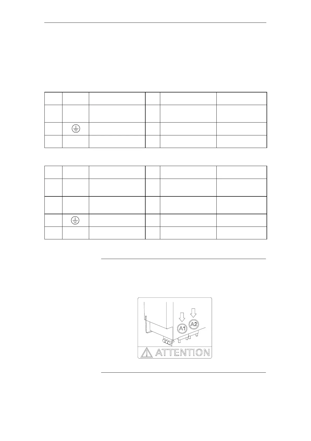
Note
For 2 --axis module, Order No.: 6SN1123 --1AB00--0CA2/0CA3, note that the
terminal arrangement of A1 and A2 differs compared to the other 2--axis
modules!
4Powe
Mo
ule
10.0411.0505.08