8
05.01
8.3 Axis expansion using a monitoring module
8-246
© Siemens AG 2008 All Rights Reserved
SIMODRIVE 611 Configuration Manual (PJU) – 05/2008 Edition
8.3 Axis expansion using a monitoring module
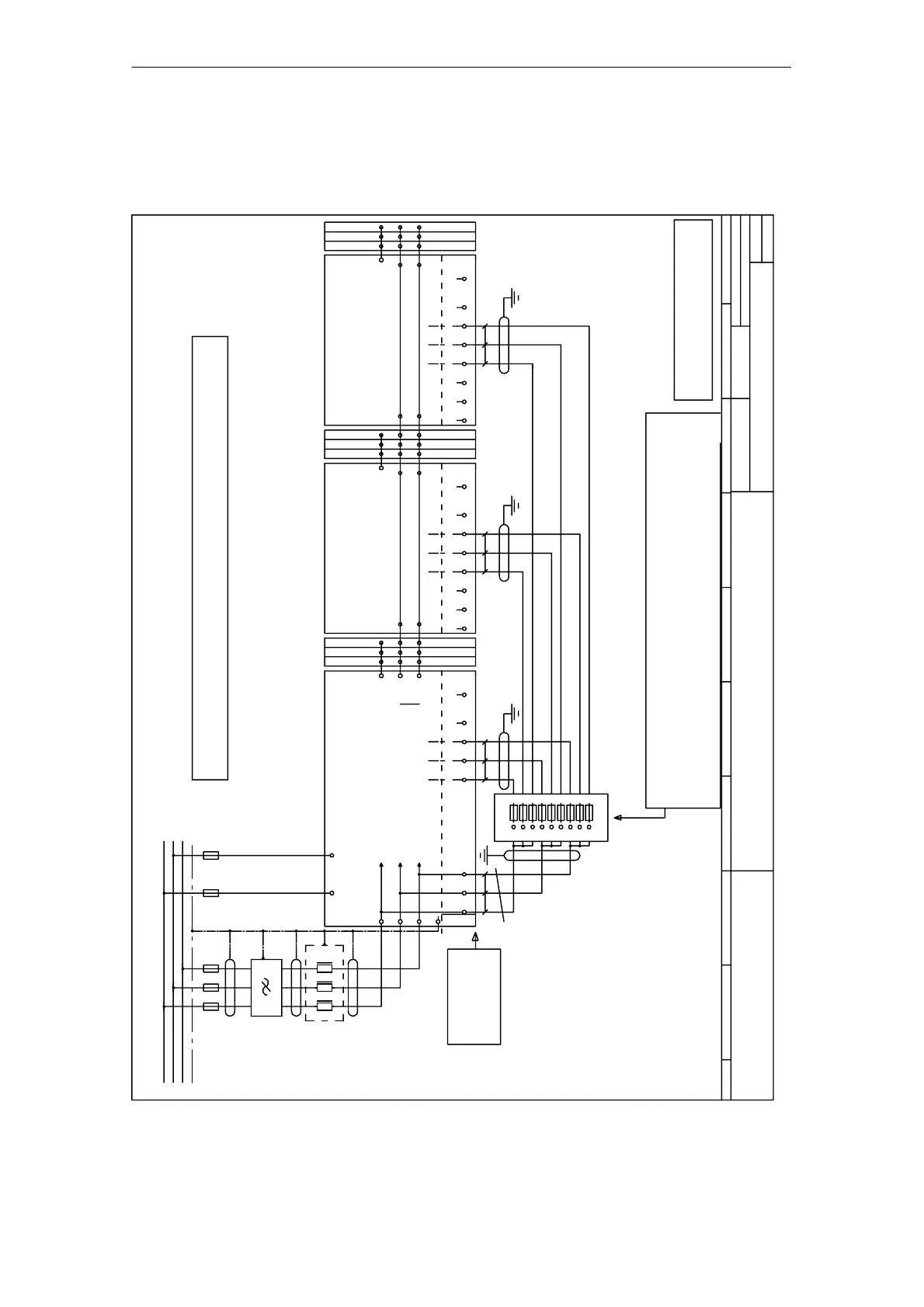
8.3.1 Connection example, power supply (standard)
See also Section 8.15, examples of correct and incorrect NE connection to the line supply
Drives
1 to n
3/PE AC 50/60 Hz 400 V
9.3.1 Connection example, power supply (standard)
9.3 Axis expansion using the monitoring module
Cable routing according to EN 60204–1/VDE 0113 Part 1:
2) Terminals L1 – L2 are only available for 80/120 kW
and 120/156 kW NE modules.
3) Rated current at V(N) = 3–ph. 400 V AC, approx. 600 mA
4) V (N) max. 415 V
Cross–section >= 1.5 qmm (>= AWG16) and
Cable length <= 3.0 m
0
1)
123
Jumpers
L3
PE
L2
L1
Remove the jumpers
1W1 – 2W1
At the NE module
1U1 – 2U1
1V1 – 2V1
PE
1V1
#
1)
1U1 1W1
W1
V1
U1
4)
1U2
1U1
1V2 1W2
1V1 1W1
UVW
L1 L2 L3
L1 L2
2)
L3
PE
L1
L2
UK10–DREHSI 6.3x32 with jumper FBI 10–12 or EB 10–12 (UL 300V), or
Phoenix ZFK 6 DREHSI 6.3x32 with jumper FBI 10–12 (UL 600V) or equivalent
UK 6.3–HESI with jumper EBS x–8 (UL 600V), or
With fuse insert 6.3x32 mm 500V/10A SIBA 70 125 40–10A (UL 500V)
Fused terminal PHOENIX CONTACT
Fused terminals 10 A
456
25.04.2001
A3431–820937
KIC
+
=
Sh.
7
All cables designated with #
must be routed so that they are short–
circuit and ground–fault proof.
89
Connecting X181:P500 to DC link P600 and X181:M500 to DC link M600 is permissible!
-Monitoring
1)
3)
2U1 2V1 P5002W1 M500
X181
NE module
DC link
P600
M600
Equipment bus
1V11U1 2U1
1)
3)
1W1 2V1
module 1
Drives
CAUTION!
1 to n
1V1P5002W1 M500
X181
1U1 2W12U1
1)
3)
1W1 2V1
X181
P500 M500
-Monitoring
module 2
Drives
1 to n
1
1 Sh.
Fig. 8-6 Connection example, power supply (standard)
8 Im
ortant Circuit Information 05.08