8
05.01
8.5 Start inhibit in the drive modules/safe standstill
8-259
© Siemens AG 2008 All Rights Reserved
SIMODRIVE 611 Configuration Manual (PJU) – 05/2008 Edition
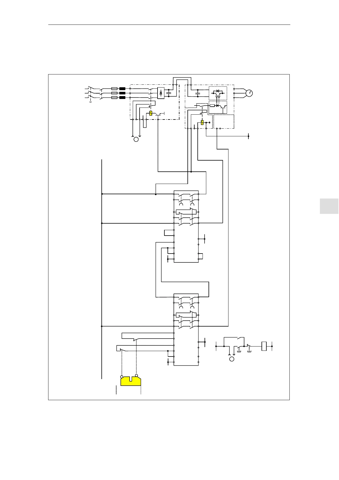
8.5.6 Example ”safe standstill” with contactor safety combination
–Q1
Main switches
Supply system
EN+
AS1
AS2
663
9
M
PV
SIMODRIVE
Closed–loop Control Module
U2 V2 W2
65
M
3
RF
n = 0
EN+
113
213
EN–
U1 V1 W1
111
48
NS1
NS2
SIMODRIVE
NE
Closed
Open
A1 Y10
Y21 Y22Y11 Y12
13
14
3TK2828
24
23 31 47 57
32 48 58Y33 Y34 PE A2
A1 Y10 Y11 Y12 Y21Y22 13
14
3TK2828
24
23 31 47 57
32 48 58Y33Y34 PE A2
IF
M
M
P24
P24
P24
–A1 –A2
–S2
–S3
EN–19
M
–S1
–K1
–K1
–S2
On
Off
1
Monitoring the internal
line contactor of the
Infeed unit
–K1
M
P24
1
Monitoring the internal
line contactor of the
Infeed unit
Line supply
Line supply
Fig. 8-11 Example, minimum circuitry for the ”safe standstill” function with SIMODRIVE 611
8 Im
ortant Circuit Information02.03