8
05.01
8.3 Axis expansion using a monitoring module
8-247
© Siemens AG 2008 All Rights Reserved
SIMODRIVE 611 Configuration Manual (PJU) – 05/2008 Edition
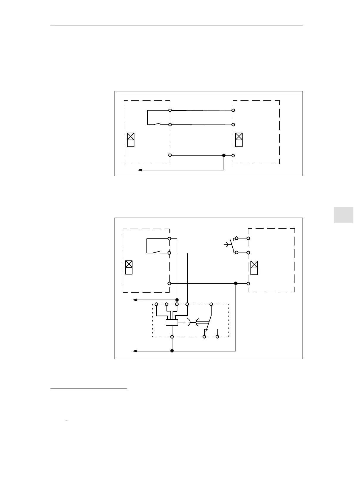
8.3.2 Connection example, pulse enable
Ready/
Error message
S1.2
72
73.1
FR– 19
1)
19 FR–
Ready/
Error message
S1.2
63 IF
9 FR+
0 V
To the external power supply
1)
2)
NE module Monitoring module
Fig. 8-7 Instantaneous shutdown, pulse enable
Ready/
Error message
S1.2
72
73.1
FR– 19
1)
19 FR–
Ready/
Error message
S1.2
63 IF
9 FR+
0 V
To the external power supply
1)
A1 A3B1 B3
A2 18
15
16
+24 V
–KT
–KT
15
18
2)
3)
NE module Monitoring module
Fig. 8-8 Delayed shutdown, pulse enable
1) Settings, S1.2 Ready/fault signal, refer to Chapter 6.2.
2) The shutdown function is shown in a simplified fashion without the contacts of the drive–related control.
3) Time relay with delayed drop–out with auxiliary voltage, e.g. 3RP1505–1AP30,
t(v) > max. braking time of the drives after the monitoring module.
Instantaneous
shutdown
Delayed shutdown
8 Im
ortant Circuit Information