4
05.01
4.3 Technical data
4-88
© Siemens AG 2008 All Rights Reserved
SIMODRIVE 611 Configuration Manual (PJU) – 05/2008 Edition
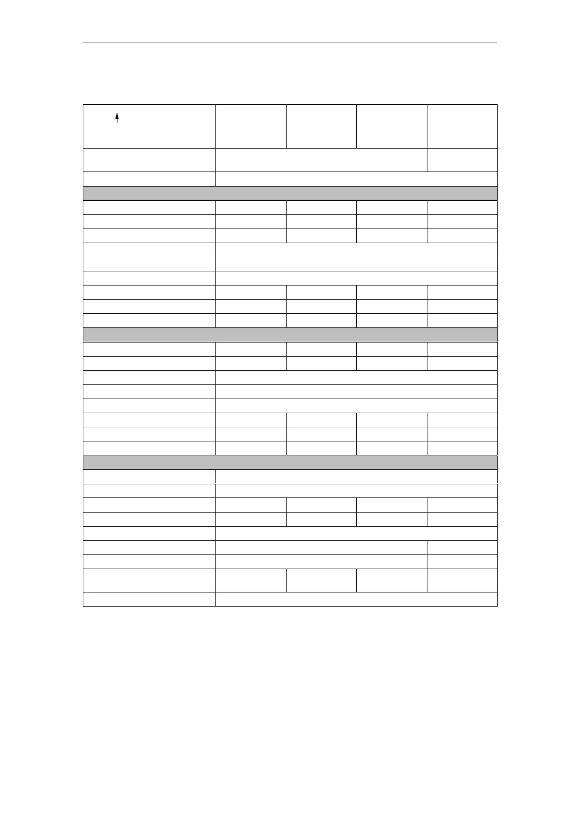
Table 4-2 Power modules in the 2–axis version
6SN112j–1AB00–
3 internal cooling
4 external cooling
0HAj 0AAj 0BAj 0CAj
Mounting frame external
cooling 6SN1162–0BA04–
0AAj 0GAj
Type of cooling Fan
For operation of induction motors
1)
Nominal current I
n
A
eff
3 5 8 24
Current for S6–40% I
S6–40%
A
eff
3 5 10 32
Peak current I
max
A
eff
3 8 16 32
Inverter pulse frequency f
0
kHz 3.2
Derating factor X
L
% 55
Power loss, total P
Vtot
W 76 118 226 538
Power loss, internal P
Vint
W 28 42 74 184
Power loss, external P
Vext
W 48 76 152 354
For operation of synchronous motors
Nominal current I
n
A
eff
3 5 9 18
Peak current I
max
A
eff
6 10 18 36
Inverter pulse frequency f
0
kHz 4
Derating factor X
L
% 55
Power loss, total P
Vtot
W 70 100 180 380
Power loss, internal P
Vint
W 27 38 69 130
Power loss, external P
Vext
W 43 62 111 250
General technical data for the regulated infeed
Input voltage V DC regulated: 600 V or 625 V DC, unregulated: U
DC
link
=U
Supply
1.35
Maximum output voltage V
eff
U
a_max
= U
DC
link
/1.4
Minimum motor current I
min
2)
A 0.6 1.1 1.8 3.6
Transistor limit current A 8 15 25 50
Efficiency 0.98
Module width mm 50 100
Weight, approx. kg 7 13.5
Maximum air flow of fan
(volumetric flow) m
3
/hr
– – 19 56
Motor connection Connectors
1) For IM operation, corresponding to the selected 4/8 kHz inverter pulse frequency, an appropriate derating must be
observed.
2) True for induction motors and applies to the no–load current.
4 Power Modules 10.0405.08