4
05.01
4.6 Interfaces and terminals
4-99
© Siemens AG 2008 All Rights Reserved
SIMODRIVE 611 Configuration Manual (PJU) – 05/2008 Edition
4.6.2 Connectable cable cross–sections
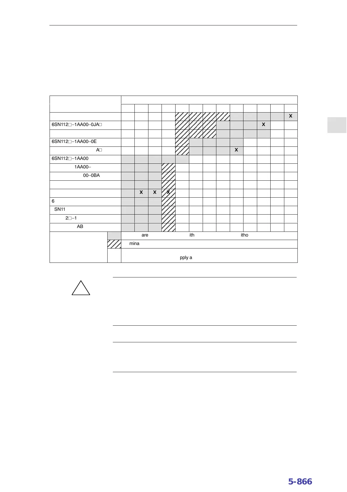
The connectable cable cross–sections can be seen in Table 4-7:
Table 4-7 Cable cross–sections that can be connected to the power module
Connection cross–section [mm
2
]
1.5 2.5 4 6 10 16 25 35 50 70 95 120 150
6SN112j–1AA00–0KAV
X
6SN112j–1AA00–0JAV
X
6SN112j–1AA00–0FAV
X
6SN112j–1AA00–0EAV
X
6SN112j–1AA00–0LAV
X
6SN112j–1AA00–0DAV X X X X X X
6SN112j–1AA00–0CAV X X X
X
6SN112j–1AA00–0BAV X X X
X
6SN112j–1AA00–0AAV X X X
X
6SN112j–1AA00–0HAV X X X
X
6SN112j–1AB00–0CAV X X X
X
6SN112j–1AB00–0BAV X X X
X
6SN112j–1AB00–0AAV X X X
X
6SN112j–1AB00–0HAV X X X
X
Key Terminal area for flexible cable with end sleeves (with or without plastic collars)
Terminal area for flexible cables with terminal pin
X
IP20 guaranteed
The user does not have to apply any additional measures.
!
Warning
The internal overload monitoring function of the power modules only protects
the cable if this is dimensioned/selected corresponding to the power module
currents. If smaller cross–sections are selected, then the user must ensure the
appropriate level of cable protection, e.g. by suitably setting the control
parameters.
Note
For UL certification, only use copper cables that have been appropriately
dimensioned/selected for the operating temperature w60 _C.
4 Power Modules10.0402.07