8
05.01
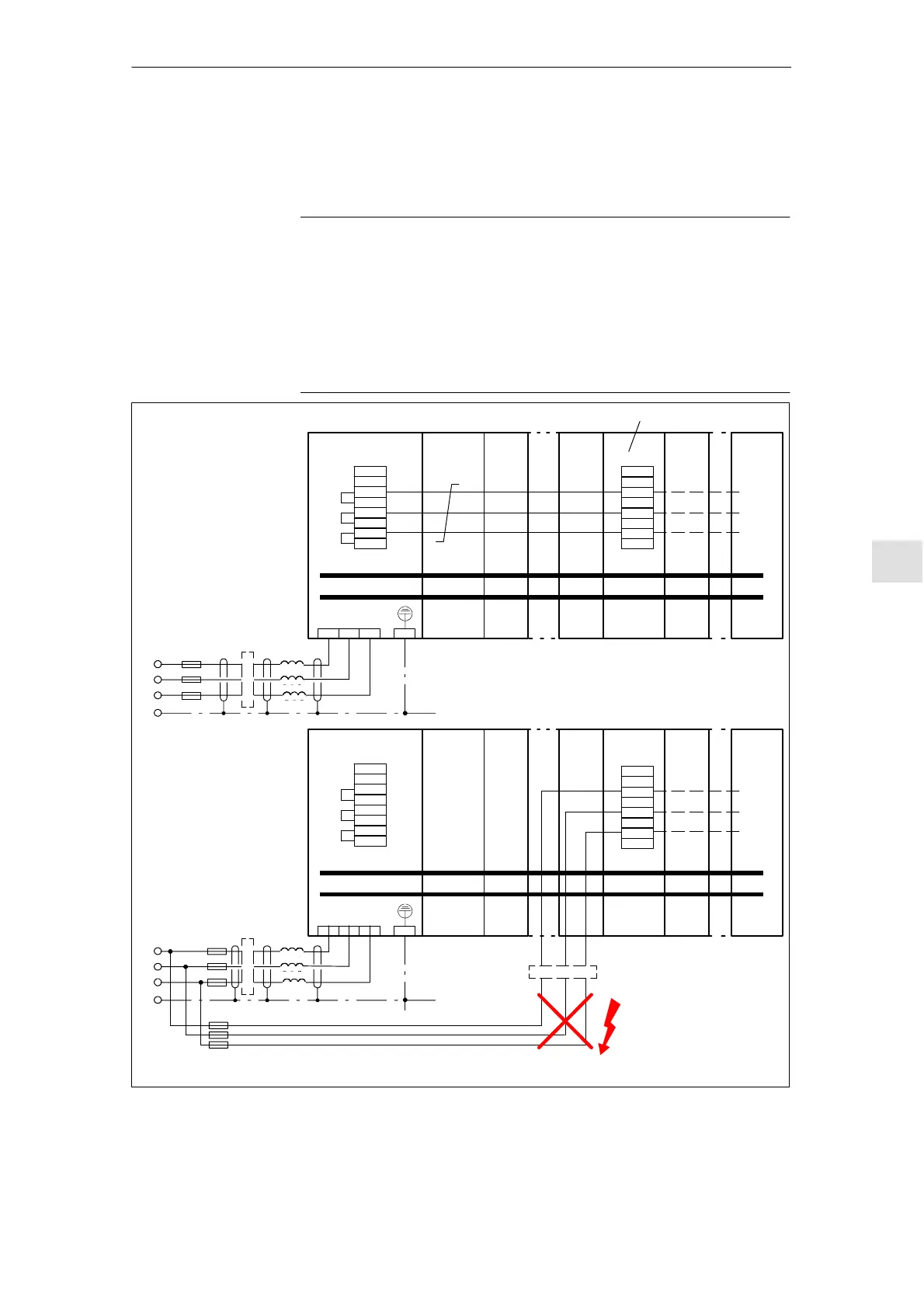
8.15 Examples of correctly and incorrectly connecting NE
8-313
© Siemens AG 2008 All Rights Reserved
SIMODRIVE 611 Configuration Manual (PJU) -- 05/2008 Edition
8.15 Examples of correctly and incorrectly connecting NE
to the line supply
8.15.1 Three--conductor connection to the line supply
Note
S All X181 connections of a drive group must be electrically switched in
parallel!
S A maximum of four monitoring modules may be c onnected at X181 of an
NE module.
S If a DC link is buffered (DC link connection), the voltage must always be
taken from between the reactor (L
K
) and the line supply infeed (NE).
S For all of the following examples, cables must be routed so that they are
short--circuit and ground--fault proof (or fuse)!
e.g. NCU PMxx
Monitoring module (MM)
P600
M600
U1 V1 W1 PE
PMxx PMxx
≤4MM
X181
M500
P500
2U1
1U1
2V1
1V1
2W1
1W1
X181
M500
P500
2U1
1U1
2V1
1V1
2W1
1W1
n.c.
n.c.
n.c.
n.c.
Correct!
e.g. NCU PMxx
P600
M600
U1 V1 W1 PE
PMxx PMxx
X181
M500
P500
2U1
1U1
2V1
1V1
2W1
1W1
X181
M500
P500
2U1
1U1
2V1
1V1
2W1
1W1
n.c.
n.c.
n.c.
n.c.
Incorrect!
≁
Filter (5 kW)
≁
L1
L
K
1)
F
N
(X A)
Filter (X kW)
PE
L2
L3
Schematic diagram
Three--conductor connection
to the line supply
NE
NE
1) Note: L
k
for 5 kW and 10 kW integrated, therefore in this case not necessary here!
2) Cable protection fuses
MM
≁
L1
L
K
1)
F
N
(X A)
Filter (X kW)
PE
L2
L3
3)
3) Consequences when
incorrectly connected to
the line supply:
S Possibly damage to the
hardware
S Possible errors on the
drive bus
2)
Twisted
cable
F
N
(T10 A)
≤4MM
Fig. 8-31 Examples of correctly/incorrectly connecting up the unit using a three--conductor connection with a maximum
of four monitoring modules connected to a line infeed module (NE module)
Im
o
n
C
cu
Info
m
on05.08