6
05.01
6.1 Description
6-153
© Siemens AG 2008 All Rights Reserved
SIMODRIVE 611 Configuration Manual (PJU) -- 05/2008 Edition
DIP switch
Signal
ready/
fault signal
I
2
t -- pre--warning
and motor
overtemperature
Drive
enable
Pulse
enable
Reset T. 112
setup
operation
3)
T. 4 8
start
Feedback
signal ,
start inhibit
Equipment
bus
X151
Monitoring
Voltage
controller
Current
setpoint
limiting
Current
controller
Pulse
generation
Control
NS1 X131
Electronics power supply
NS1 NS2
NS1 NS2
AS1 AS2112 48 19
EN--
9R15151044457
MN24N15P1 5P24
639964
EN+
Safety relay, start inhibit
Power supply and
signals
Unit enable
V
act
5.372 73.1 73.2 74 5.25.1
DC link
sensi ng
V
mot
= 600 V/625 V
6
2)
1
1)
S1
2
1)
3
1)
4
1)
5
1)
Gating/
control
unit
I
Act
ual
T
max. power section
P600
M600
Line supply
rectification and
synchronization
DC link pre-
charging circuit
Signal,
line contactor
Commutating
reactor
1) When supplied, OFF
2) When supplied ON
3) Jumpers closed when supplied
T. 1U1--2U1, 1V1--2V1, 1W1 --2W1
T. 9--112--48
T. N S 1 -- NS 2
M500P500
4)
1W1 2W1 1V1 2V1 1U1 2U1U1 V1 W1
L1 L2 L3
Line supply, 3--ph. 400 V
AC (415/480 V)
113 111 213
X131 (refer to Chapter 8.2)
PE
PE1L2
L2
L1
L1
Line supply, 2--ph. 400 V
AC (415/480 V)
F1, F2
NS2
Pre--charging
contactor
Line
contactor
3)
3)
Settings , refer to
Chapter 6.2
5)
6)
4) Jumper open in shipped
state
5) T. L1, L2 only available for I/R modules
80 and 120 kW
6) T. 113 for UI modules, 5 and 10 kW
not present
AB
100 k
AB
DC link controller
Note:
For a description of the
interface, refer to Chapter 6.5
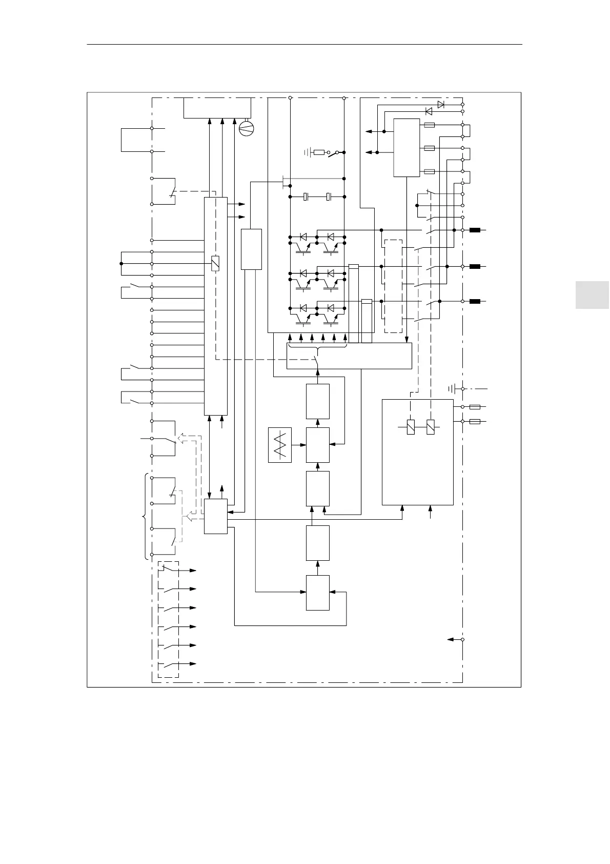
Fig. 6-4 Block diagram, line supply infeed module (I/R)
6 Infee
Mo
ule
11.05