6
05.01
6.1 Description
6-152
© Siemens AG 2008 All Rights Reserved
SIMODRIVE 611 Configuration Manual (PJU) – 05/2008 Edition
M600
P600
X351
X111
X121
X141
X161
X171
X172
X181
L1 L2 X131
red
yellow
red
5 V voltage
level faulted
Unit ready
(DC link
pre–charged)
DC link
overvoltage
Electronics power
supply faulted
Device is not ready,
no enable signal (term.
63, 64 or 48)
Line supply fault
Line supply connection
Equipment
bus
DC link connection
red
green
red
LED
displays
5.3
5.2
5.1
63
9
9
64
19
74
73.2
73.1
72
7
45
44
10
15
15
R
9
112
48
111
113
NS2
NS1
AS2
AS1
Relay contact
Ready signal
NC
contact
NO
contact
Relay contact for group signal I
2
t
and motor overtemperature
Pulse enable
Enable voltage
Drive enable
Reference potential for enable
voltage
Enable voltage
P24
P15
N15
N24
M
M
RESET (R+term.15)
Enable voltage
Set–up operation
Contactor energization, start
213
Signaling contact,
line contactor
Enable signal for internal line
contactor
Signaling contact, start inhibit (NC
contact)
M500
P500
2U1
1U1
2V1
1V1
2W1
1W1
DC link power supply for buffering
power failures
External infeed for the electronics power supply
External infeed for the electronics power supply
External infeed for the electronics power supply
1)
1)
1) Jumpers inserted when the equipment is supplied
LED display
1)
nc
nc
U1
PE
W1V1
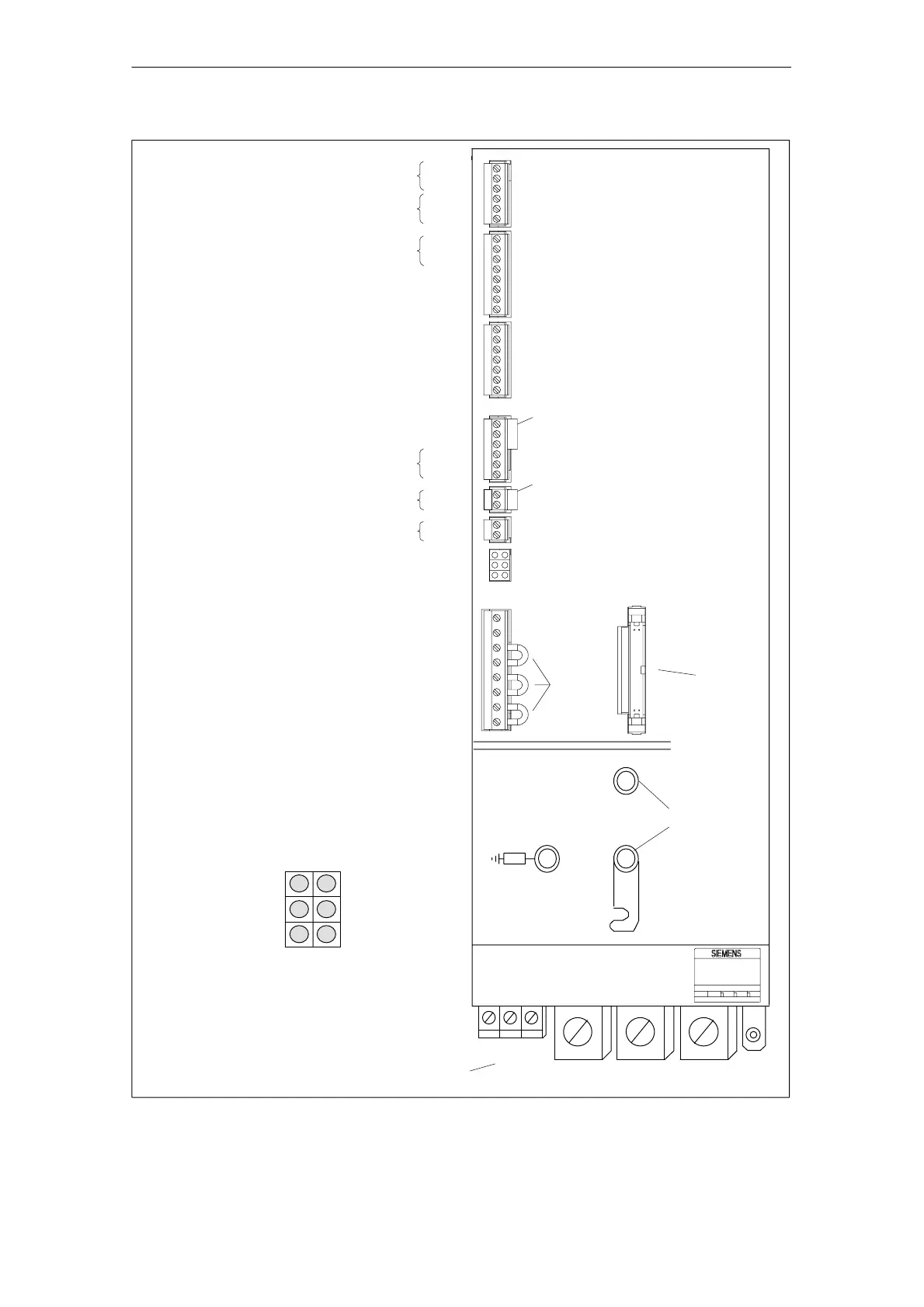
Fig. 6-3 Infeed/regenerative feedback module (80 and 120 kW I/R module) interfaces
6 Infeed Modules 11.0505.08
 Loading...


